Pipelining: Basic and Intermediate Concepts
- Appendix C in Computer Architecture A Quantitative Approach (6th) by Hennessy and Patterson (2017)
Introduction
- This appendix includes …
- Data path implications
- Hazards
- Examining performance of pipelines
- Based on the basic five stage RISC pipeline
- Interaction between pipelining and instruction set design
- Exceptions and their interaction with pipelining
- Extension of the five-stage pipeline to handle floating point instructions
- Dynamic scheduling and use of scoreboards
What is pipelining?
- Pipelining:
- An implementation technique whereby multiple instructions are overlapped in execution
- Takes advantage of parallelism that exists among the actions needed to execute an instruction
- Like an assembly line
- Comprises pipe stages or pipe segments
- Exploits parallelism among the instructions in a sequential instruction stream
- Not visible to programmer
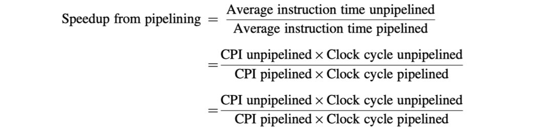
- Performance:
- Throughput of an instruction pipeline: How often an instruction exists the pipeline
- Processor cycle: time for moving an instruction one step down
- Balance the length of each pipeline stage (cycles for each step)
- The time per instruction on the pipelined processor
A Simple Implementation of a RISC Instruction Set
- RISC implementation without pipelining
- Branch instructions: 3 cycles
- Store instructions: 4 cycles
- Other instructions: 5 cycles
-
Instruction Fetch cycle (IF)
- Send the program counter (PC) to memory
- Fetch the current instruction
- Update the PC $\leftarrow$ PC + 4
-
Instruction Decode / register fetch cycle (ID)
- Decode the instruction
- Read the registers corresponding to register source specifiers
- Do the equality test for a possible branch
- Sign-extend the offset field if needed
- Compute the possible branch target address by adding the sign-extended offset to the incremented PC
-
Fixed field decoding:
- Parallelize decoding and register reading (good for perf, bad for energy)
- Parallelize decoding and sign-extension of the immediate field for loads and ALU (store has immediate field in different location)
-
Execution / effective address cycle (Ex)
- Memory reference
- Register-Register ALU instruction
- Register-Immediate ALU instruction
- Conditional branch
-
Memory access (MEM)
- The memory does a read/write using the effective address
-
Write-back cycle (WB)
- Write the result in to the register file (Register-Register ALU instruction or load instruction)
The Classic Five-Stage Pipeline for a RISC Processor
- The simplest pipelining: Start new instruction on each clock cycle
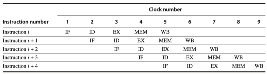
- The pipeline can be thought as a series of data paths shifted in time
- Focus on CC5, a steady-state situation
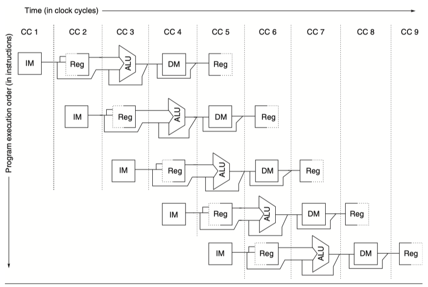
- Focus on CC5, a steady-state situation
- How not to make resource conflict (Look at CC5 in the figure above)
-
Separate instruction (IM) and data (DM) memories (or caches)
- Need higher bandwidth
-
Register file used in two stages
- One for reading in ID and One for writing in WB
- So, two reads and one writes every clock cycle
- Read and write to the same register?
- Perform register write in the first half of the clock cycle, register read in the second half
-
PC?
- IF stage: PC $\leftarrow$ PC+4 and
- ID stage: adder to compute potential branch target
- Ex stage: ALU evaluation of the branch condition
-
Separate instruction (IM) and data (DM) memories (or caches)
- Prevent interference between pipe stages
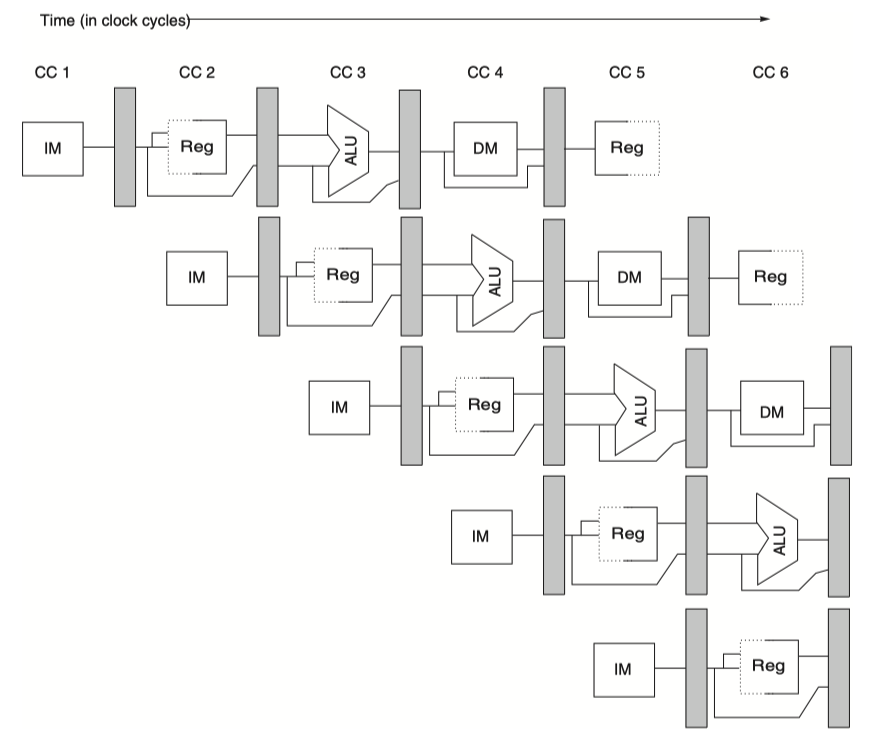
- Insert pipeline registers
- Helpful for neighboring and non-neighboring stages
- Non-neighboring stages? :
- Register value for
storeneeds to wait for two cycles to be used in MEM stage. Passing two pipeline register makes it work. - ALU results need to wait until WB
- Register value for
- Non-neighboring stages? :
Basic Performance Issues in Pipelining
- Execution time of each instruction does not decrease
- Program runs faster, even though no single instruction runs faster
- Limits on the practical depth of a pipeline
- Limits arise from imbalance among pipe stages and pipelining overhead
The Major Hurdle of Pipelining - Pipeline Hazard
-
Hazards
- Prevent the next instruction in the instruction stream from executing during its designated clock cycle
-
Three classes of hazards
-
Structural hazards
- Arise from resource conflicts
- Primarily occur in special purpose functional units
-
Data hazards
- When an instruction depends on the results of a previous instruction
-
Control hazards
- Arise from the pipelining of branches and other instructions that change the PC
-
Structural hazards
Performance of Pipelines With Stalls


Data Hazards
- When an instruction $i$ and its subsequent instruction $j$ both use register $x$
-
Read After Write (RAW) hazard:
- $j$ reads $x$ before $i$ writes back its result to $x$
- $j$ reads wrong $x$ value
- $j$ should stall
-
Write After Read (WAR) hazard:
- $i$ reads $x$ after $j$ writes back its result to $x$
- $i$ reads wrong $x$ value
- Not happen in simple five stage pipeline
- Possible when $i$ and $j$ reordered in dynamically scheduled pipelines
-
Write After Write (WAW) hazard:
- $i$ writes to $x$ after $j$ writes to $x$
- Wrong $x$ value in future
- Not happen in simple five stage pipeline
- Possible when $i$ and $j$ reordered in dynamically scheduled pipelines
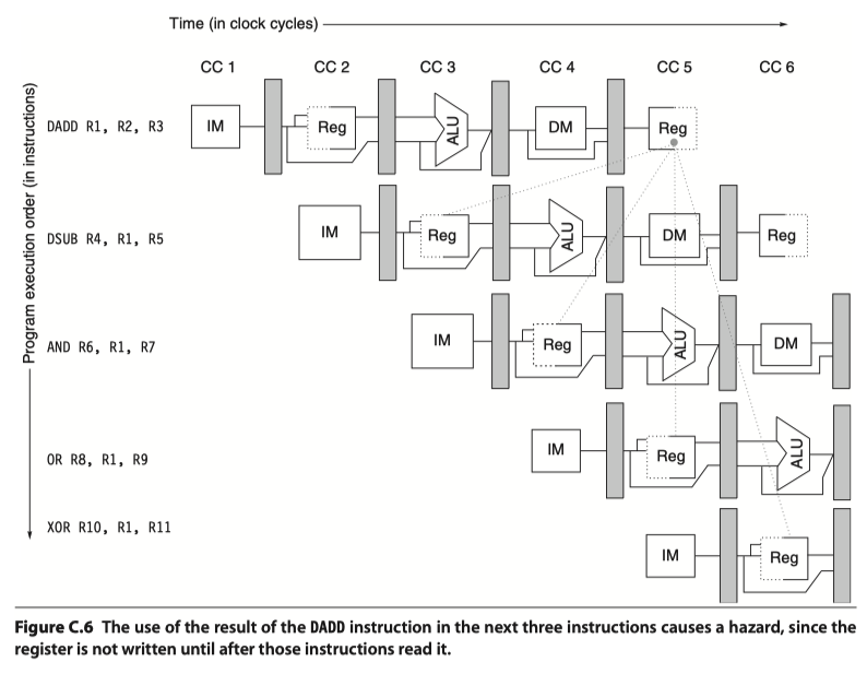
- Example
- add x1, x2, x3
- sub x4, x1, x5
- and x6, x1, x7
- or x8, x1, x9
- xor x10,x1,x11
-
RAW hazards: add-sub, add-and
-
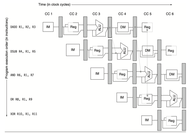
Minimizing Data Hazard Stalls by Forwarding
-
Forwarding, bypassing, short-circuiting
- ALU results in EX/MEM and MEM/WB pipeline registers is fed back to the ALU inputs
- Forward hardware detects RAW hazards, selects the forwarded results as ALU input
- A set of instructions that depends on the ADD result uses forwarding paths to avoid the data hazard
-
Forwarding, bypassing, short-circuiting
-
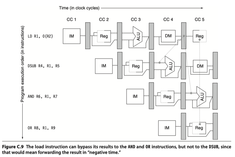
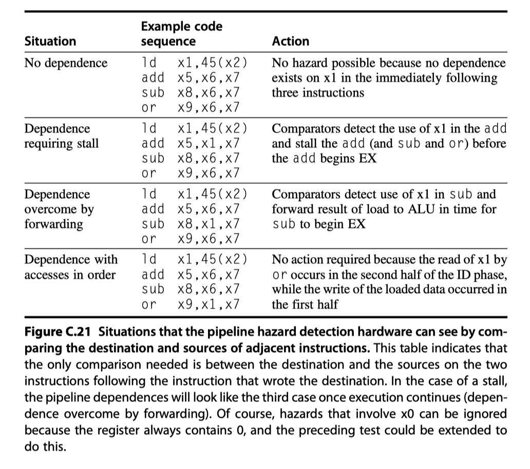
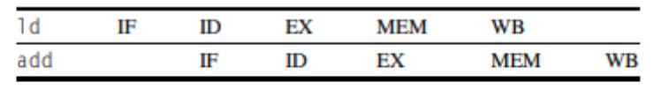
Data Hazards Requiring Stalls
- Not all data hazards can be handled by bypassing
- Example
- ld x1, 0(x2)
- sub x4, x1, x5
- and x6,x1,x7
- or x8,x1,x9
- RAW hazard: Need ”Backwarding” to negative time, impossible.
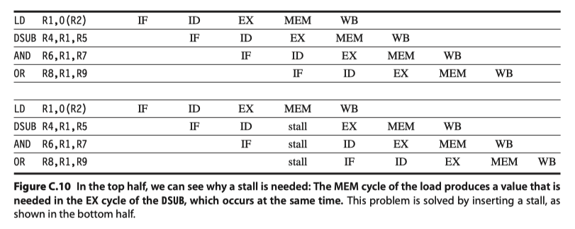
-
Pipeline interlock
- Detects hazard and stalls the pipeline until the hazard is cleared
- So, introduces stall or bubble
Branch Hazards
- One stall cycle for every branch: 10~30% performance loss!
- Reducing Pipeline Branch Penalties
- Scheme#1: Freeze or Flush
- Hold or delete the pipeline until the branch destination is known
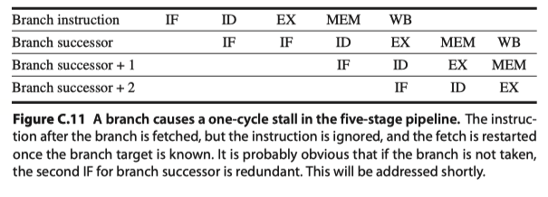
- Hold or delete the pipeline until the branch destination is known
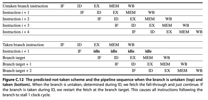
- Scheme#2: Predicted-not-taken / Predicted-untaken
- Treat every branch as not taken, until the branch outcome is definitely known.
- Have to know when the state might be changed by an instruction and how to “back out” such a change
- Scheme#3: Predicted-taken
- Scheme#4: Branch delay
- Execution order: (branch instruction)$\rightarrow$(Sequential successor = Branch delay slot)$\rightarrow$(Branch target if taken)
- Confusion: What if the sequential successor is also a branch? Don’t allow it!
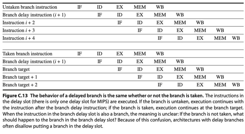
- Scheme#1: Freeze or Flush
Reducing the Cost of Branches Through Prediction
- Deeper pipelines, more potential penalty of branches
-
Predict branches!
- Strategy#1: Low-cost static schemes w/ information available in compile time
- Strategy#2: Predict branches dynamically based on program behavior
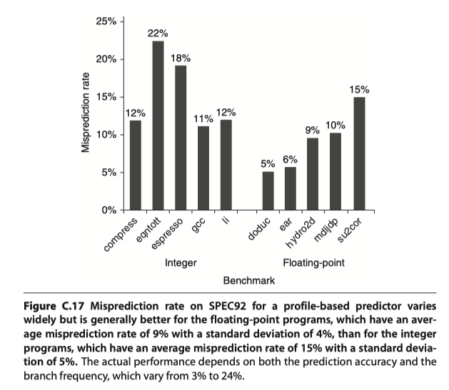
Static Branch Prediction
- Use profile information collected from earlier runs
- Success of static branch prediction
Dynamic Branch Prediction and Branch-Prediction Buffers
- Scheme#1: Branch-prediction buffer = Branch history table
- A small memory indexed by the lower portion of the address of the branch instruction
- A bit that tells whether the branch taken or not
- 1bit-prediction scheme: a prediction gets inverted if it miss once
- 2bit-prediction scheme: a prediction gets inverted if it miss twice
- Implemented as a small, special cache,
- or as a pair of bits attached to each block in the instruction cache
- 2bit-scheme illustration
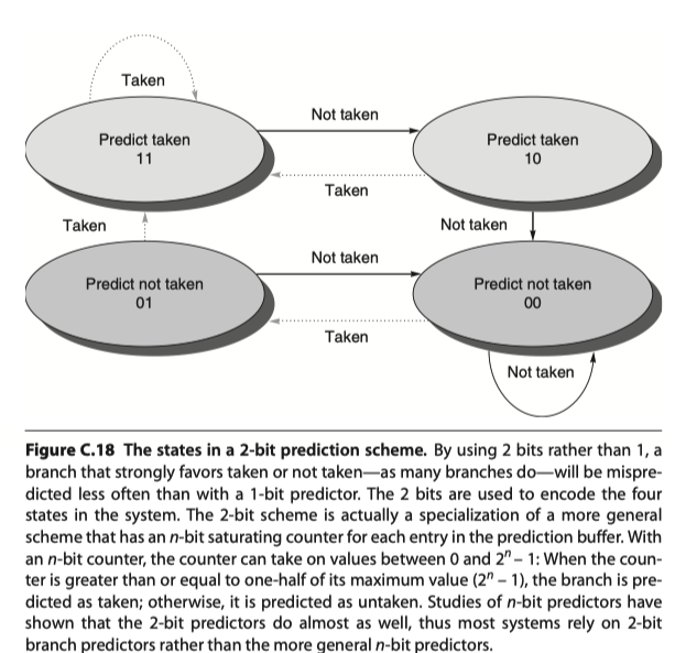
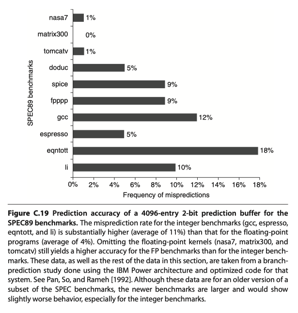
- Accuracy? 82%~99%
How Is Pipeline Implemented?
A Simple Implementation of RISC-V
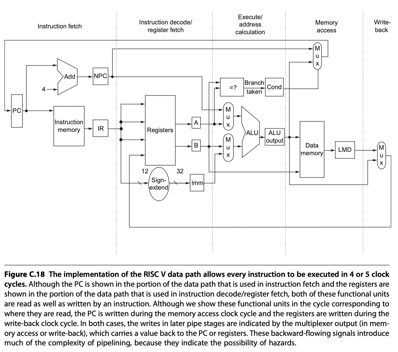
- Unpipelined version
- Integer subset of RISC-V
- Load-store word
- Branch equal
- Integer ALU operations
5 clock cycles
-
Instruction fetch cycle (IF)
- IR $\leftarrow$ Mem[PC];
- NPC $\leftarrow$ PC+4;
-
Instruction decode / Register fetch cycle (ID)
- A $\leftarrow$ Regs[rs1];
- B $\leftarrow$ Regs[rs2];
- Imm $\leftarrow$ Sign-extended immediate field of IR;
- Fixed field decoding: Decoding is done in parallel with reading registers
-
Execution / Effective address cycle (EX)
- Memory reference: ALUOutput $\leftarrow$ A + Imm;
- Register-register ALU instruction: ALUOutput $\leftarrow$ A $func$ B;
- Register-immediate ALU instruction: ALUOutput $\leftarrow$ A $op$ Imm;
- Branch:
- ALUOutput $\leftarrow$ NPC + (Imm « 2);
- Cond $\leftarrow$ (A==B)
- Effective address and execution cycles can be combined into a single clock cycle
-
Memory access / branch completion cycle (MEM)
- PC $\leftarrow$ NPC
- Memory reference:
- LMD (load memory data register) $\leftarrow$ Mem[ALUOutput]
- or Mem[ALUOutput] $\leftarrow$ B;
- Branch:
- if (cond) PC $\leftarrow$ ALUOutput
-
Write-back cycle (WB)
- Register-register or Register-immediate ALU instruction:
- Regs[rd] $\leftarrow$ ALUOutput;
- Load instruction
- Regs[rd] $\leftarrow$ LMD;
- Register-register or Register-immediate ALU instruction:
- Simplified and unpipelined RISC-V implementation!
A Basic Pipeline for RISC V
-
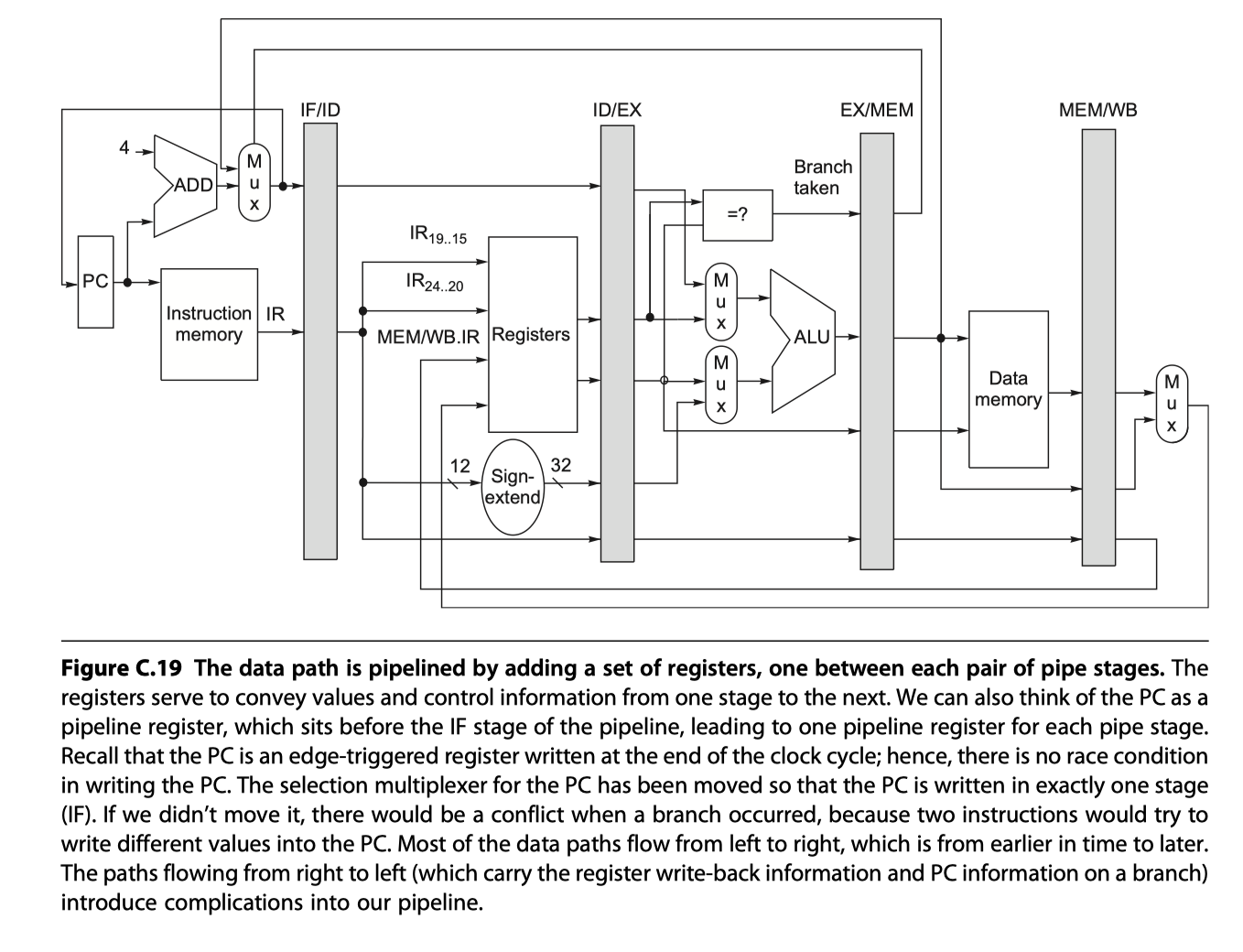
Pipelined version
-
Control signals for the four multiplexers (four MUXs from the figure above, and one hidden MUX)
-
2 MUXs in ALU stage depend on the instruction type. Refer instruction in IF/ID reg
- Top ALU MUX: branch or not?
- Bottom ALU MUX: register-register or not?
-
1 MUX in IF stage
- PC+4 or the value of the branch target from EX/MEM.ALUOutput
- Controlled by EX/MEM.Cond
-
2 MUXs in WB stage
- to choose between Load or ALU?
- to choose destination register
-
2 MUXs in ALU stage depend on the instruction type. Refer instruction in IF/ID reg
Implementing the Control for the RISC V Pipeline
- Instruction issue: Moving an instruction from ID to EX
- When to detect hazards and determine forwarding?
- Approach#1: ID phase
- Approach#2: At the beginning of a clock cycle that uses an operand (EX and MEM)
-
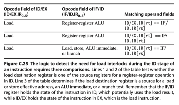
Load interlock
- How the interlock for a RAW hazard with the source coming from a load instruction can be implemented by a check in ID?
- Situations that must be handled
-
Implementing load interlock
- Instruction $i(=load)$ in EX stage
- Instruction $j$ that need the loaded value in ID stage
- All possible hazard situations. Detect!
- Once a hazard has been detected, the control unit must …
- Insert the pipeline stall $\rightarrow$ Change the control portion of ID/EX to be 0 (=no-op)
- Prevent the instructions in IF and ID stages from advancing $\rightarrow$ Recirculate IF/ID registers
- Implementing the forwarding logic by
- A comparison of the destination registers of the instruction (IR) contained in the EX/MEM (ALUOutput) and MEM/WB (Load memory data) stages against the source registers of the IR contained in the ID/EX and EX/MEM registers.
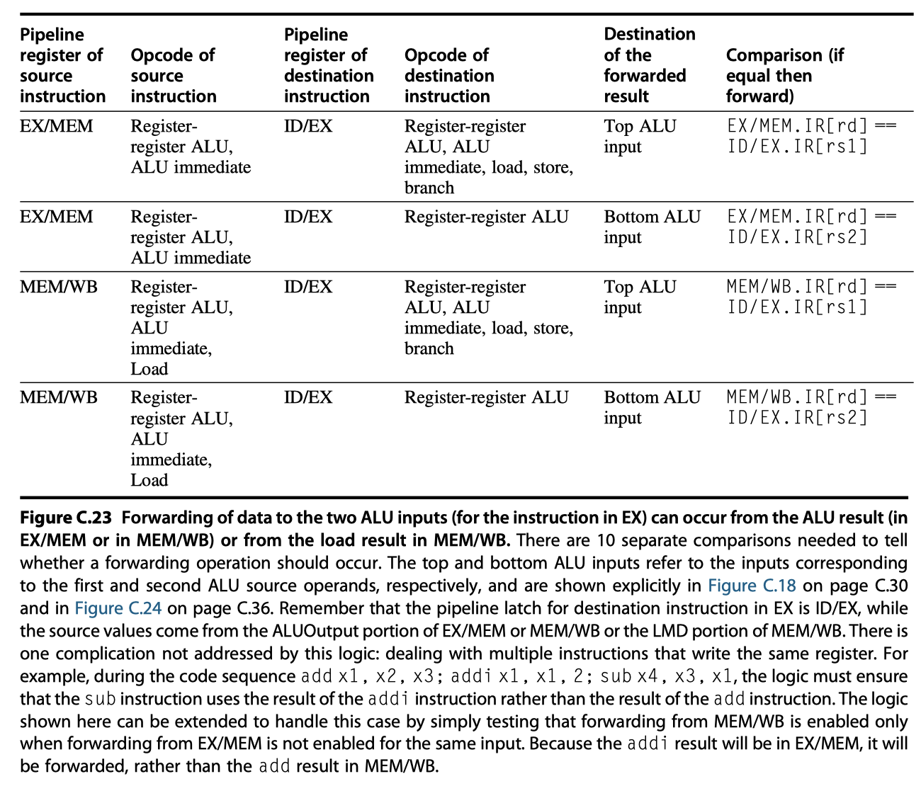
- When a forwarding path needs to be enabled
- $\rightarrow$ Enlarge multiplexers at the ALU
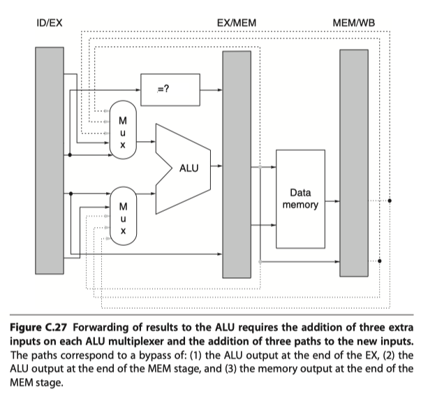
- $\rightarrow$ Enlarge multiplexers at the ALU
- A comparison of the destination registers of the instruction (IR) contained in the EX/MEM (ALUOutput) and MEM/WB (Load memory data) stages against the source registers of the IR contained in the ID/EX and EX/MEM registers.
Dealing With Branches in the Pipeline
- Add separate adder that computes the branch target address during ID
What Makes Pipelining Hard to Implement?
Dealing With Exception
-
Can an instruction safely change the state of the processor in exceptional situations?
- Types of Exceptions
- I/O devices request
- Invoking an operating system service from a user program
- Tracing instruction execution
- Breakpoint (programmer-requested interrupt)
- Integer arithmetic overflow
- FP arithmetic anomaly
- Page fault (not in main memory)
- Misaligned memory accesses (if alignment is required)
- Memory protection violation
- Using an undefined or unimplemented instruction
- Hardware malfunctions
- Power failure
-
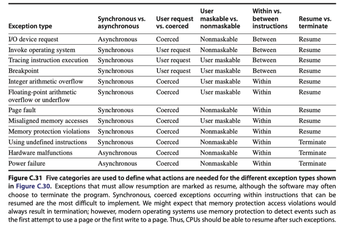
Five Categories of Requirements on Exceptions
- Synchronous $vs$ Asynchronous
- User requested $vs$ Coerced
- User maskable $vs$ User nonmaskable
- Within $vs$ Between Instructions
- Resume $vs$ Terminate
-
Exception events and their requirement categories
-
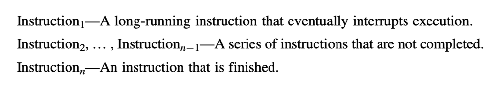
Stopping and Restarting Execution
- Most difficult exceptions when they
- Occur within instructions (EX or MEM pipe stages)
- Must be restartable
- Example) A virtual memory page fault
- How to save the pipeline states?
- Force a trap instruction on the next IF
- Turn off all writes from the current instructions / fetching next-instructions
- Save the PC of the faulting instruction for later returning
- Most difficult exceptions when they
-
Precise exception
- All instructions ahead of the fault instruction are completed
- And then the fault instruction can be restarted without any effect from exception
- Need to store the source operands as well
- Exceptions in RISC V
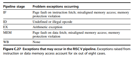
- Consider this instruction sequence
- At the same time, possibly,
- A data page fault in MEM stage of load
- An arithmetic exception in EX stage of add instructions
- Handle only the exception from prior instruction, handle the other later
-
Out of order exception cases?
- A data page fault in MEM stage of load
- A instruction page fault in IF stage of add
-
Handling out-of-order exception?
- Guarantee that all exceptions will be seen on instruction $i$ before any are seen on $i+1$ !
- Post all exceptions caused by given instruction in a status vector associated with the instruction
- For each exception indication in a vector, all possible data-writing associated to the instruction are turned off
- Hardware must be prepared to prevent the store from completing (due to potential exception of store in MEM stage)
- Consider this instruction sequence
Instruction Set Complications
- An instruction is “Committed”: The instruction is guaranteed to complete
- To maintain a precise exception model, most processors with such instructions have the ability to back out any state changes made before the instruction is committed
- eg1. “String copy operation” in Intel or IBM360: The state of the partially completed instruction is always in the registers to enable exception and restoration
- eg2. Condition codes
- eg3. Pipelining in multicycle operations: pipeline the microinstruction execution!
Extending the RISC V Integer Pipeline to Handle Multicycle Operations
- How to extend integer RISC V for floating point operation?
- RISC V with four separate functional units
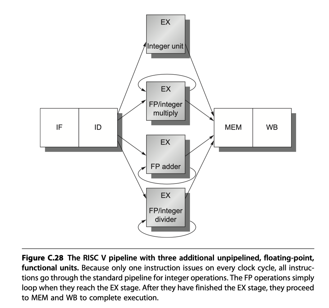
- The main integer unit with load / store / integer ALU / branches
- FP and integer multiplier
- FP adder for FP add, subtract, conversion
- FP and integer divider
-
FP functional unit performance?
- Latency of functional units: The number of intervening cycles between an instruction that produces a result and an instruction that uses the result
- The initiation or repeat interval : The number of cycles that must elapse between issuing two operations of a given type
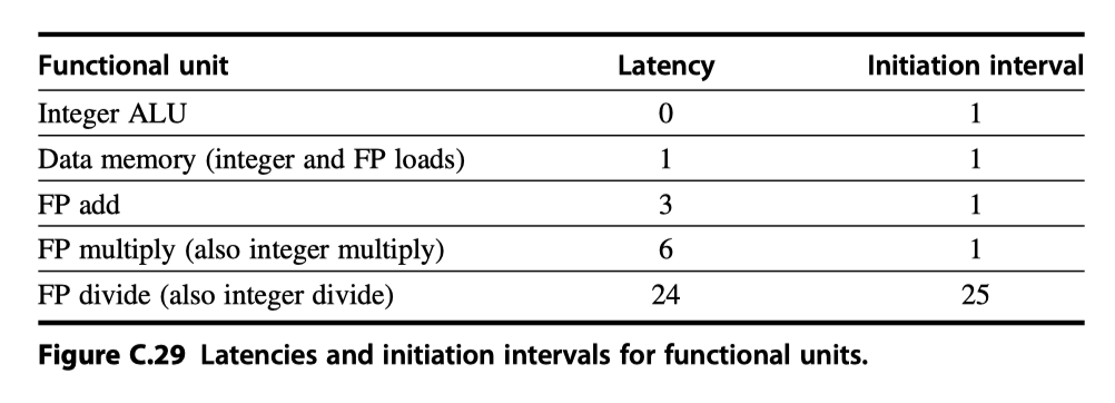
- Pipeline latency = (The depth of the execution pipeline) - 1
- A pipeline that supports multiple outstanding FP operations
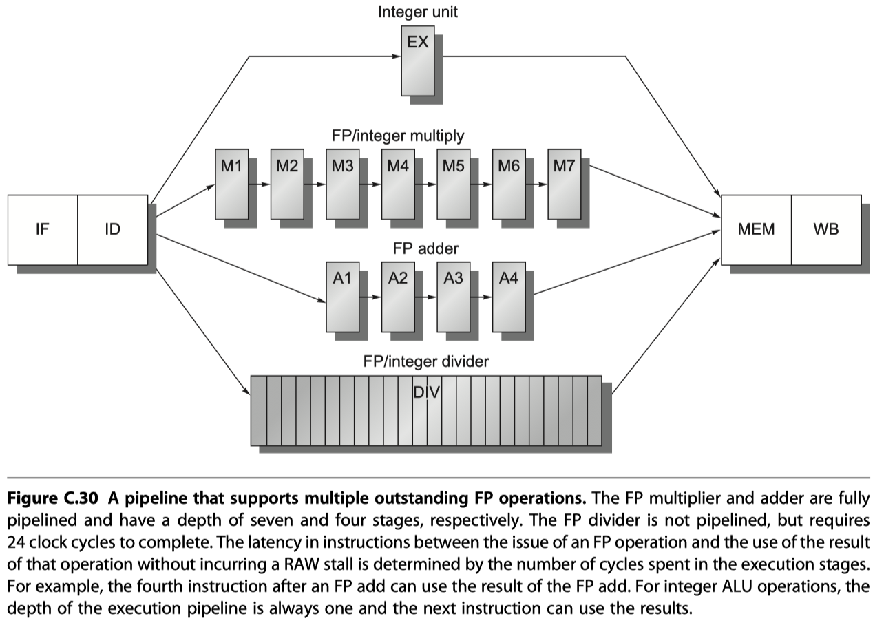
- FP multiplier / adder $\rightarrow$ Fully pipelined
- FP divider $\rightarrow$ Not pipelined, requires 24 cycles to complete
- $i.e.$ 24 cycle latency, 25 cycle initiation interval
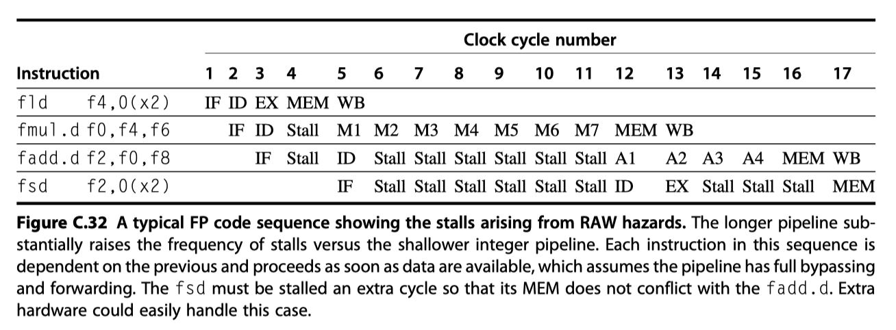
Hazards and Forwarding in Longer Latency Pipelines
- What happen with longer latency pipelines?
- If not pipelined (eg. FP divider), Structural hazard can occur $\rightarrow$ Detect $\rightarrow$ Stall
- Varying running time $\rightarrow$ # register writes $\ge$ 1
- No longer in order $\rightarrow$ Write after write (WAW) hazards are possible
- No longer in order $\rightarrow$ Problems with exception
- Stalls for RAW hazards will be more frequent
-
RAW hazard
-
Structural hazard from the single register port of FP register file
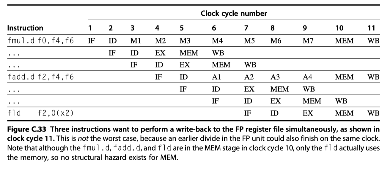
- At cycle 11 in Fig C.33, all three instructions reach WB and want to write the register file
- Let’s detect and enforce access to the write port
- Interlock implementation #1:
- Track the use of the write port (with a shift register) in the ID stage
- and stall an instructions before it issues
- Interlock implementation #2:
- Stall a conflicting instruction
- when it tries to enter either the MEM or WB stage
- Heuristic: To give priority to the unit with the longest latency
- Interlock implementation #1:
-
WAW hazard problem
- The result of fadd.d in Fig C.33 is overwritten without any instruction ever using it!
- How to handle?
- Approach #1: Delay issue of the load (fld) instruction until fadd.d enters MEM
- Approach #2: Stamp out the result of the fadd.d by detecting the hazard and changing the control so that the fadd.d does not write its result
- Assuming detection in ID stage,
-
Check for structural hazards
- Wait until the required function unit is not busy
-
Check for a RAW data hazards
- Wait until the source regs are not listed as pending destinations in a pipeline regs that will not be available when this instruction needs the result
- eg. if an instruction in ID is FP operation with f2 as destination, then f2 cannot be listed as a destination in ID/A1 … or A2/A3.
-
Check for a WAW data hazard
- Determine if any instructions in A1, … D, … M7 has the same register destination as this instruction.
-
Check for structural hazards
Maintaining Precise Exceptions
- Problem from instructions with no dependency
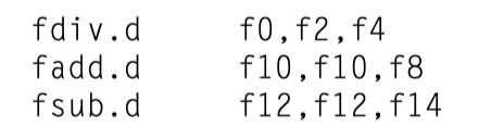
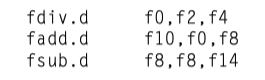
- fadd.d and fsub.d complete before fdiv.d completes
- i.e. Out-of-order completion
- If fadd.d completed, fsub.d caused an exception, fdiv.d is still running,
- Then Imprecise exception!!
- Four approaches to dealing with out-of-order completion
- Ignore the problem and settle for imprecise exceptions (1960s, 1970s)
- eg. Switch between fast imprecise mode and slow precise mode
- Buffer the results of an operation until all the operations that were issued earlier are complete
- History file: Keeps track of the original values of registers
- Future file: Keeps the newer value of a registers
- Keep enough information so that trap-handling routines can create a precise sequence for the exception
- Hybrid scheme that allows the instruction issue to continue only if it is certain that all the instructions before the issuing instruction will complete without causing an exception
- Ignore the problem and settle for imprecise exceptions (1960s, 1970s)
Performance of a Simple RISC V Pipeline
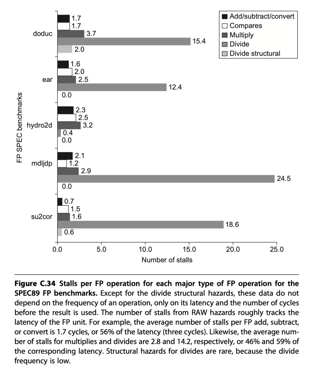
-
#stall cycles for each type of FP operation on a per-instance basis $\sim$ latency
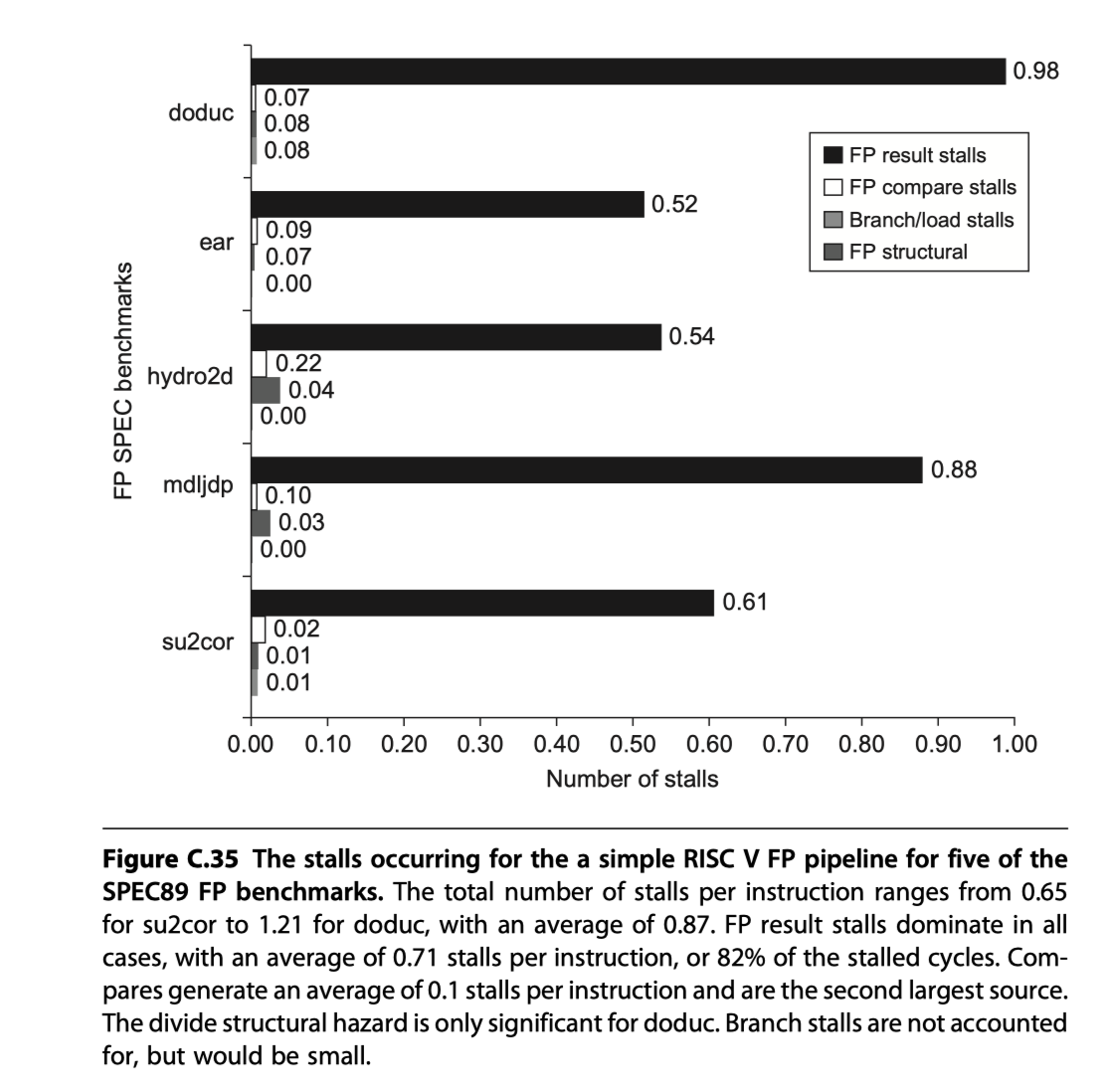
-
The complete breakdown of integer and FP stalls for five SPECfp benchmarks
Putting It All Together: The MIPS R4000 Pipeline
-
MIPS R4000 Implementation
- 8 stage:
- Deeper than 5 stage
- Decomposing the memory access: Superpipelining
- Higher clock rate
-
IF: First half of instruction fetch
- PC selection, initiate instruction cache access
-
IS: Second half of instruction fetch
- complete instruction cache access
- RF: Instruction decode, register fetch, hazard checking, instruction cache hit detection
-
EX: Execution
- Effective address calculation, ALU operation, branch-target computation, condition evaluation
-
DF: Data fetch
- First half of data cache access
- DS: Second half of data fetch, completion of data cache access
- TC: Tag check (Check data cache hit)
- WB: Write-back for loads and register-register operations
- 8 stage:
-
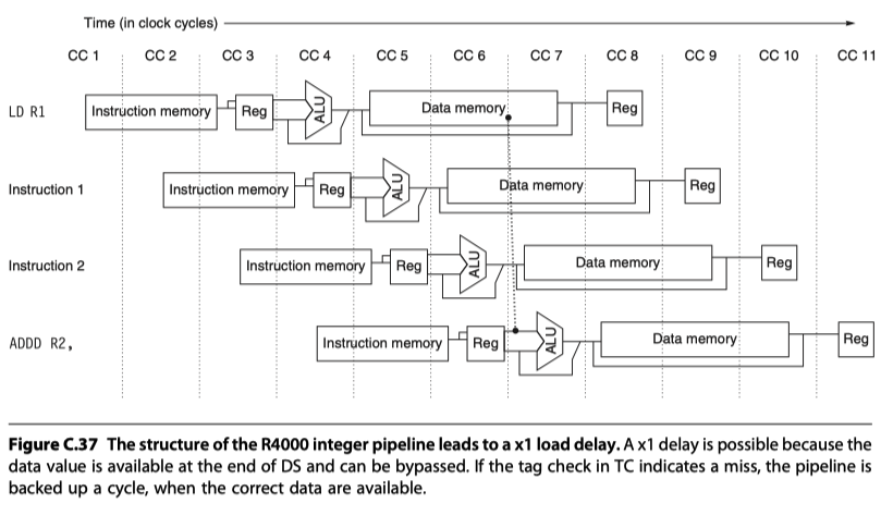
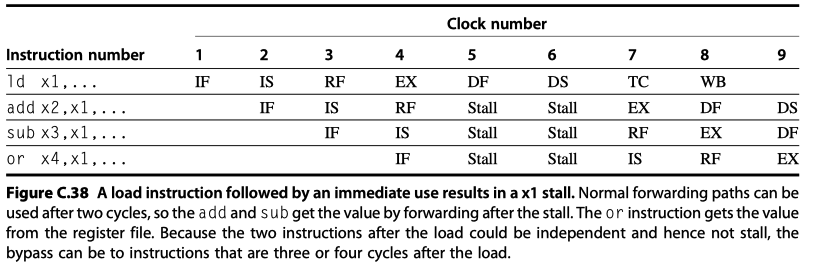
Load Delay:
- Load followed by immediate use of the data
- Need 2 cycle stall with forwarding
-
Branch Delay:
- Basic delay: 3 cycles (Branch condition at the end of EX)
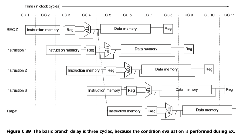
- Single cycle by predicted-not-take strategy for the remaining two cycles of the branch delay
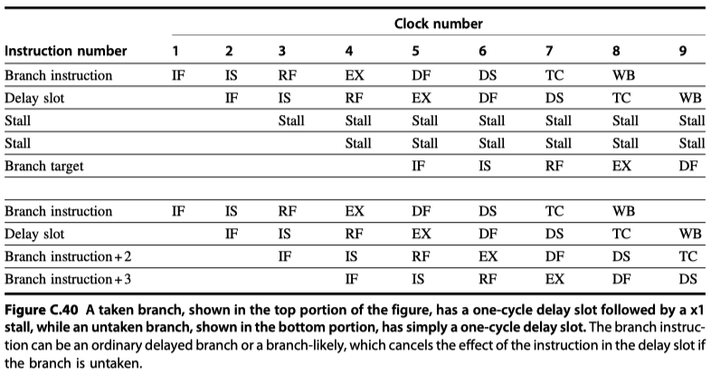
- Untaken: 1 cycle delay
- Taken: 1-cycle delay slot followed by 2 idle cycles
- Due to large penalty cycles in deeper pipelining:
- After R4000, all MIPS implementation use of dynamic branch prediction
- Basic delay: 3 cycles (Branch condition at the end of EX)
-
Pipeline interlocks
- x1 branch stall penalty on a taken branch
- Any data hazard stall from using load result
- Increased #levels of forwarding for ALU operations
- Four possible sources for an ALU bypass
- EX/DF, DF/DS, DS/TC, TC/WB
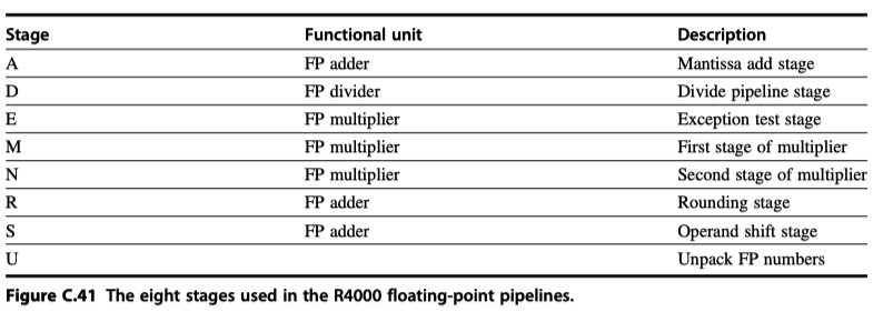
Floating-Point Pipeline
- Three functional units:
- A floating-point (FP) divider
- A FP multiplier
- A FP adder: Use the final step of MULT or DIV
- Negate = 2 cycles, Square root = 112 cycles
- 8 Stages in FP
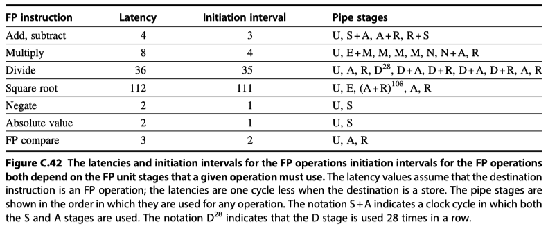
-
Latency, initiation rate, pipeline stages by DFP operation
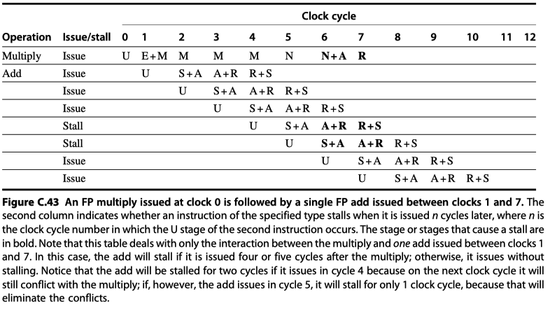
- Stall for two-instruction sequences
-
MULT-ADD
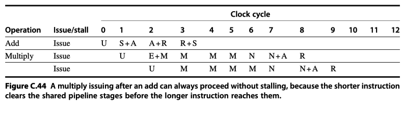
-
ADD-MULT
-
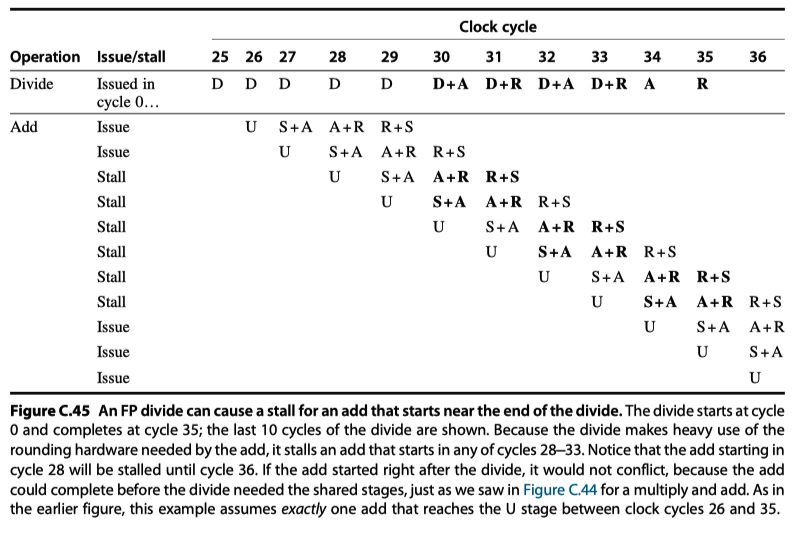
DIV-ADD
-
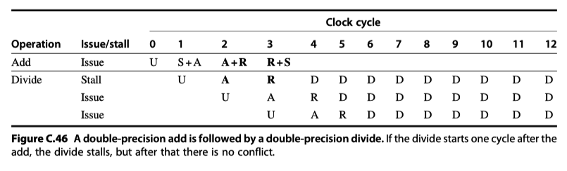
Double precision ADD-Double precision DIV
-
MULT-ADD
Performance of the R4000 Pipeline
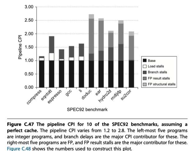
- Four major causes of pipeline stalls or losses
- Load stalls (See above)
- Branch stalls (See above)
- FP result stalls: RAW hazard for an FP operand
- FP structural stalls: Conflicts for functional units in the FP pipeline
Cross-Cutting Issues
RISC Instruction Sets and Efficiency of Pipelining
- Use simple instructions!
- Easier to schedule code to achieve efficiency
- With RISC instruction set, separate instructions may be individually scheduled either by compiler or dynamic hardware scheduling techniques
- No room for CISC instruction set for efficient schedule
Dynamically Scheduled Pipelines
-
Compiler attempts to schedule instructions to avoid hazard
- a.k.a Static scheduling
-
Dynamic scheduling
- Hardware rearranges the instruction execution to reduces the stalls
- Eg. Scoreboarding technique of the CDC6600
-
Structural and data hazards are checked during instruction decoding (ID) stage in RISC V pipeline. When an instruction could execute properly, it was issued from ID
- Separate issue process into two parts
- Checking the structural hazards
- Waiting for the absence of a data hazard
-
Out-of-Order Execution
- Begin execution as soon as their data operands are available
-
Split ID pipe stage into two stages
- Issue: Decode instructions, check for structural hazards
- Read operands: Wait until no data hazard, then read operands
Dynamic Scheduling With a Scoreboard
-
Scoreboarding allows instructions to execute out of order when there are sufficient resources and no (all types of) data dependences
- Avoid OoO-related hazards
-
WAR hazard (which doesn’t exist in RISC V in-order pipeline )
- May arise when instructions execute out-of-order
- Potential WAR hazard if fsub.d is executed before fadd.d
-
WAW hazard:
- would occur if the destination of the fsub.d were f10
-
WAR hazard (which doesn’t exist in RISC V in-order pipeline )
-
Scoreboard
- Goal: Maintain an execution rate of one instruction per clock cycle
- When next instruction to execute is stalled,
- other instructions can be issued and executed if they do not depend on any active or stalled instruction
- Responsible for (1) instruction issue, (2) execution, (3) hazard detection
- To take advantage of OoO execution, multiple instructions can be in their EX stage simultaneously
- $\rightarrow$ (1) Multiple functional units, (2) pipelined functional units, or (1+2) both
- eg. CDC6600: 16 functional units, 4 floating point units, 5 units for memory references, 7 units for integer operations
-
RISC V with Scoreboard
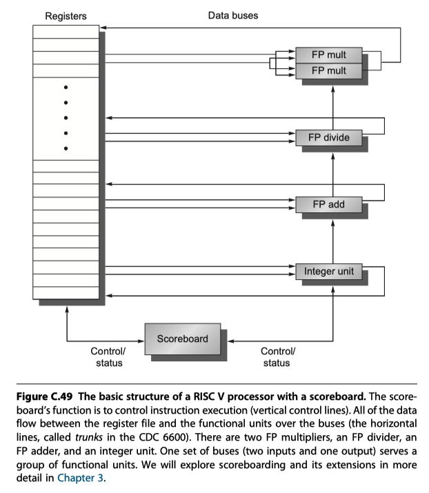
- Simple case: 2 FP multipliers, 1 FP adder, 1 FP divide unit, sigle integer unit
- Every instruction goes through scoreboard
- A record of the data dependences is constructed
- The scoreboard determines
-
when the instruction can read registers and begin execution
- If not able to begin execution, it monitors every change in the hardware and decides $when$ the instruction can execute
- when an instruction can write its result to the destination register
-
when the instruction can read registers and begin execution
- All hazard detection and resolution are centralized in scoreboard
- Four steps (replace ID/EX/WB steps)
-
Issue:
- Check if (1) no functional unit conflict (structural hazard) and (2) no other active instruction has the same destination register (WAW hazard),
- No hazard $\rightarrow$ issues the instruction to the functional unit and update its internal data structure
- Hazard $\rightarrow$ the instruction issue stalls
- Buffer between instruction fetch and issue to fill
- Check if (1) no functional unit conflict (structural hazard) and (2) no other active instruction has the same destination register (WAW hazard),
-
Read operands:
- The scoreboard monitors the availability of the source operands
- $i.e.$ Check if no active instruction is going to write it (RAW hazards)
-
Execution:
- When the result is ready, it notifies the scoreboard that it completed execution
-
Write result:
- Check for WAR hazards and stalls the completing instruction, if necessary
- WAR hazard? fadd.d and fsub.d that both use f8. The scoreboard stall fsub.d until fadd.d reads f8.
- Completing instruction cannot write its results with WAR hazard case, which means …
- there exists a preceding instruction that has not read its operands, and …
- One of the operands is the same registers as the result of the competing instruction
- Then, the benefit of forwarding reduces
-
Issue:
Reference
- Computer Architecture A Quantitative Approach (6th) by Hennessy and Patterson (2017)
- Notebook: Computer Architecture Quantitive Approach
Notes Mentioning This Note
Instruction-Level Parallelism and Its Exploitation
Instruction-Level Parallelism and Its Exploitation
Table of Contents
- Pipelining: Basic and Intermediate Concepts
- Introduction
- The Major Hurdle of Pipelining - Pipeline Hazard
- How Is Pipeline Implemented?
- What Makes Pipelining Hard to Implement?
- Extending the RISC V Integer Pipeline to Handle Multicycle Operations
- Putting It All Together: The MIPS R4000 Pipeline
- Cross-Cutting Issues
- Reference