Review of Memory Hierarchy
- Appendix B in Computer Architecture A Quantitative Approach (6th) by Hennessy and Patterson (2017)
Introduction
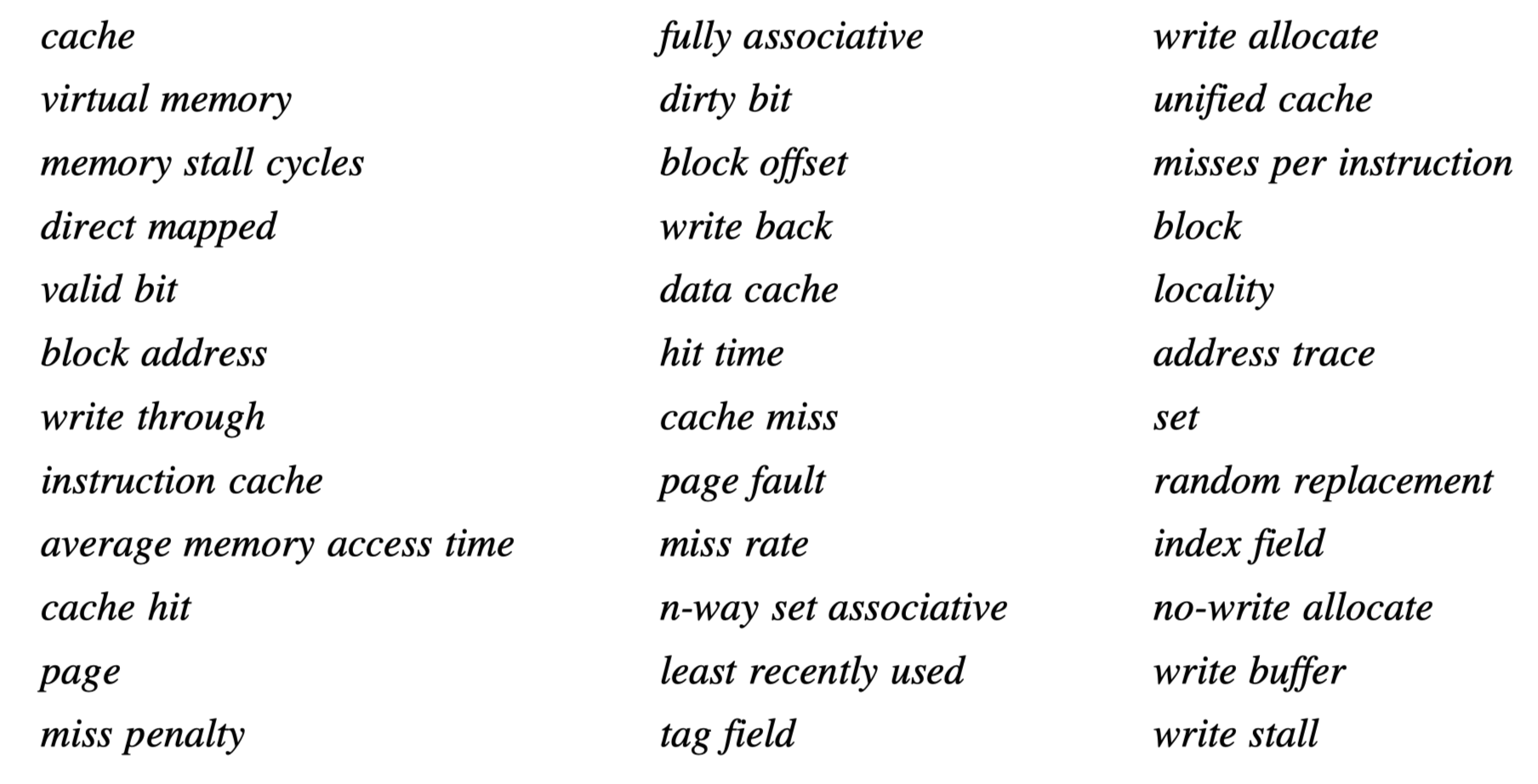
- A quick review of the following 36 terms. Check Chapter 7 in Computer Organization and Design for better understanding
- Cache
- A memory given to the highest or first level of memory hierarchy encountered once the address leaves the processor
- Take advantage of locality!
- Temporal locality vs spatial locality
- Cache hit if the requested data by processor is found in cache
- Cache miss
- Handled by hardware
- In-order execution $\rightarrow$ Pause or stall
- Out-of-order execution $\rightarrow$ The instruction with cache-miss should wait, but other instructions may proceed during the miss
- Delay from Latency and bandwidth
- Block or line in a cache:
- A fixed-size collection of data containing the requested word
- Retrieved from memory and placed into the cache
- Virtual memory
- Some objects may reside on disk
- The address space is usually broken into fixed-size blocks, called pages
- Each page resides either in main memory or on disk
-
palt:
- When the requested data is not found in both cache and main memory
- The entire page is moved from the disk to main memory
- Handled by software
- The processor is not stalled, usually by switching to some other task
Cache Performance Review

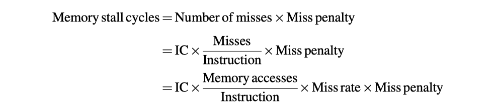
(Miss rate: Cache miss per memory access)


Four Memory Hierarchy Questions
-
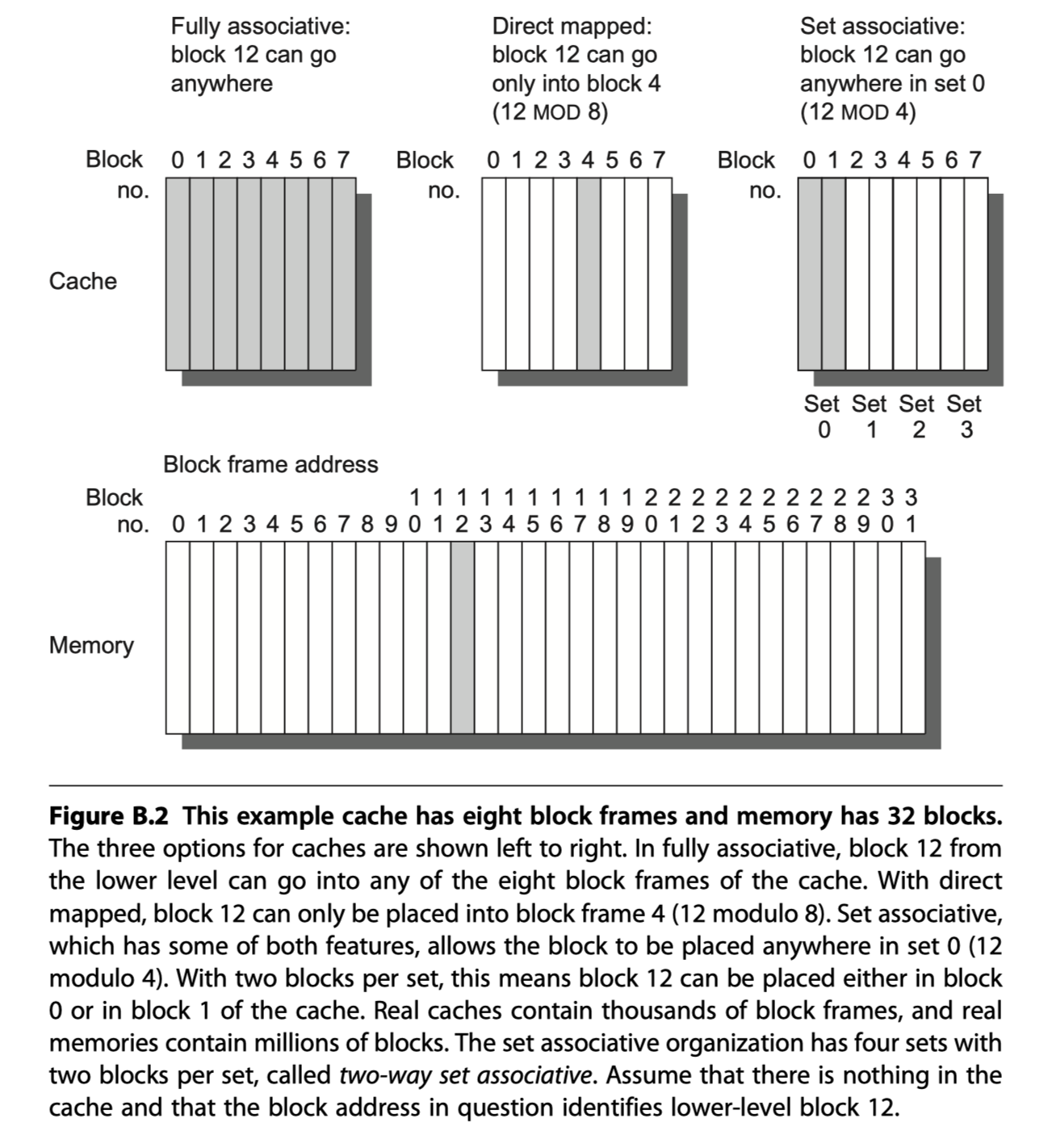
Q1: Where can a block be placed in the upper level? (block placement)
- Direct mapped: A block is mapped to only one place in the cache
- Eg. (Block address) MOD (#Blocks in a cache)
- One-way set associative
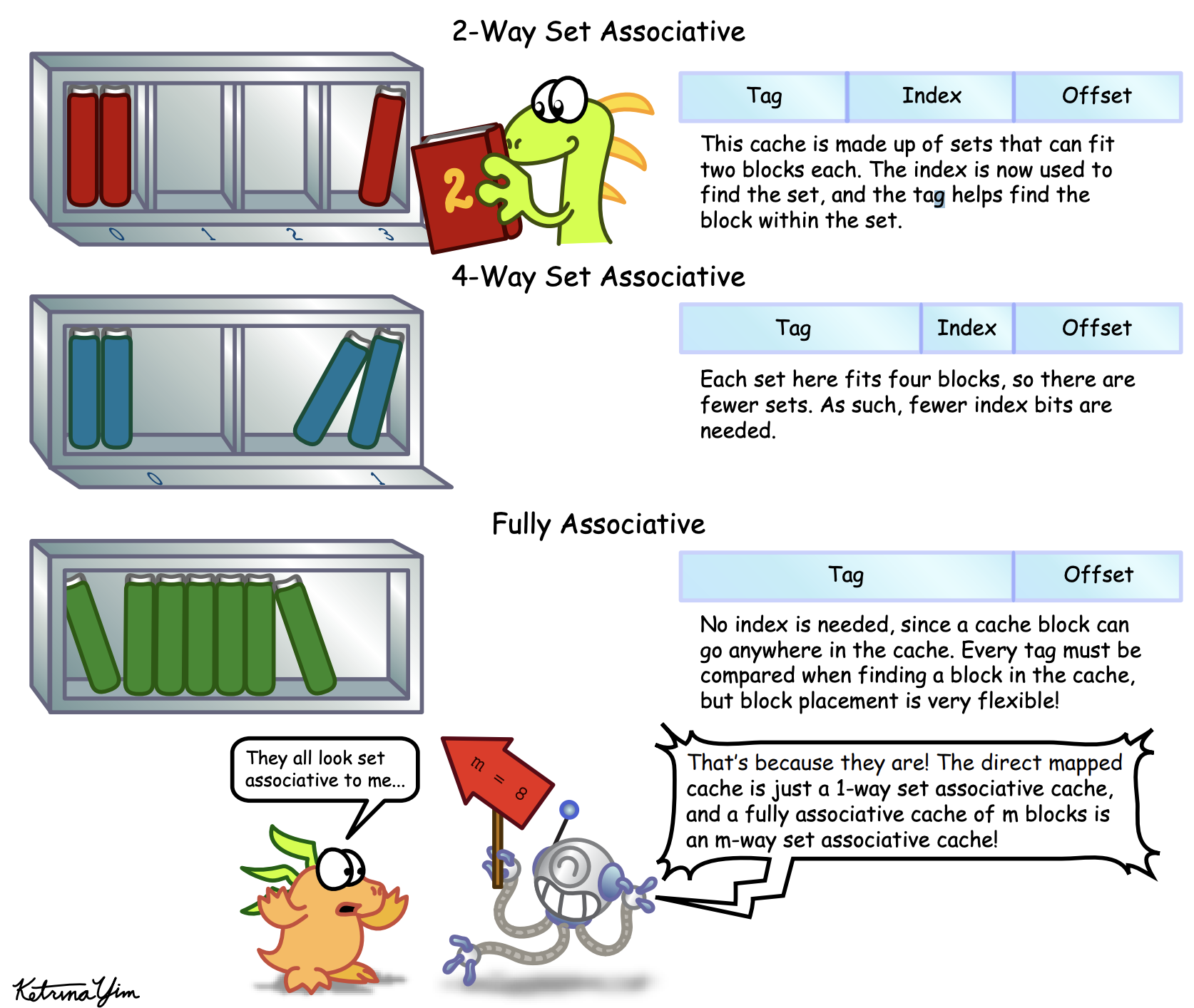
- Fully associative: A block can go anywhere in the cache
- Set associative: A block is mapped to a restricted set of places in the cache
- Set is chosen by bit selection: (Block address) MOD (#Sets in a cache)
- N-blocks in a set? $\rightarrow$ N-way set associated cache
- Direct mapped: A block is mapped to only one place in the cache
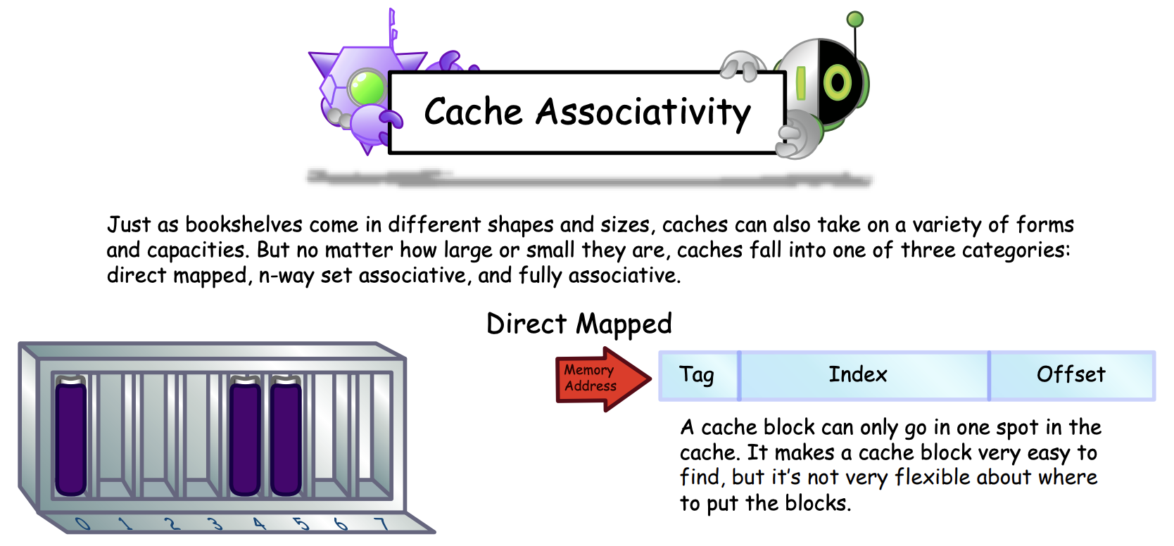
 (Image source: http://csillustrated.berkeley.edu/PDFs/handouts/cache-3-associativity-handout.pdf)
-
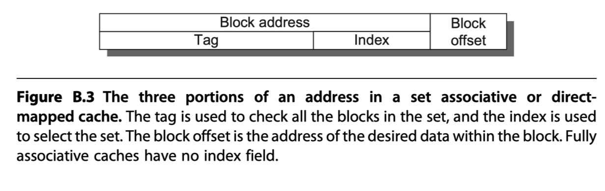
Q2: How is a block found if it is in the upper level? (block identification)
- Processor address = Block address + Block offset (select the desired data in the block)
- Block address = Tag(Compared against it for a hit) + Index (Used to select the set to be checked)
- All possible tags are searched in parallel
- Need valid bits
-
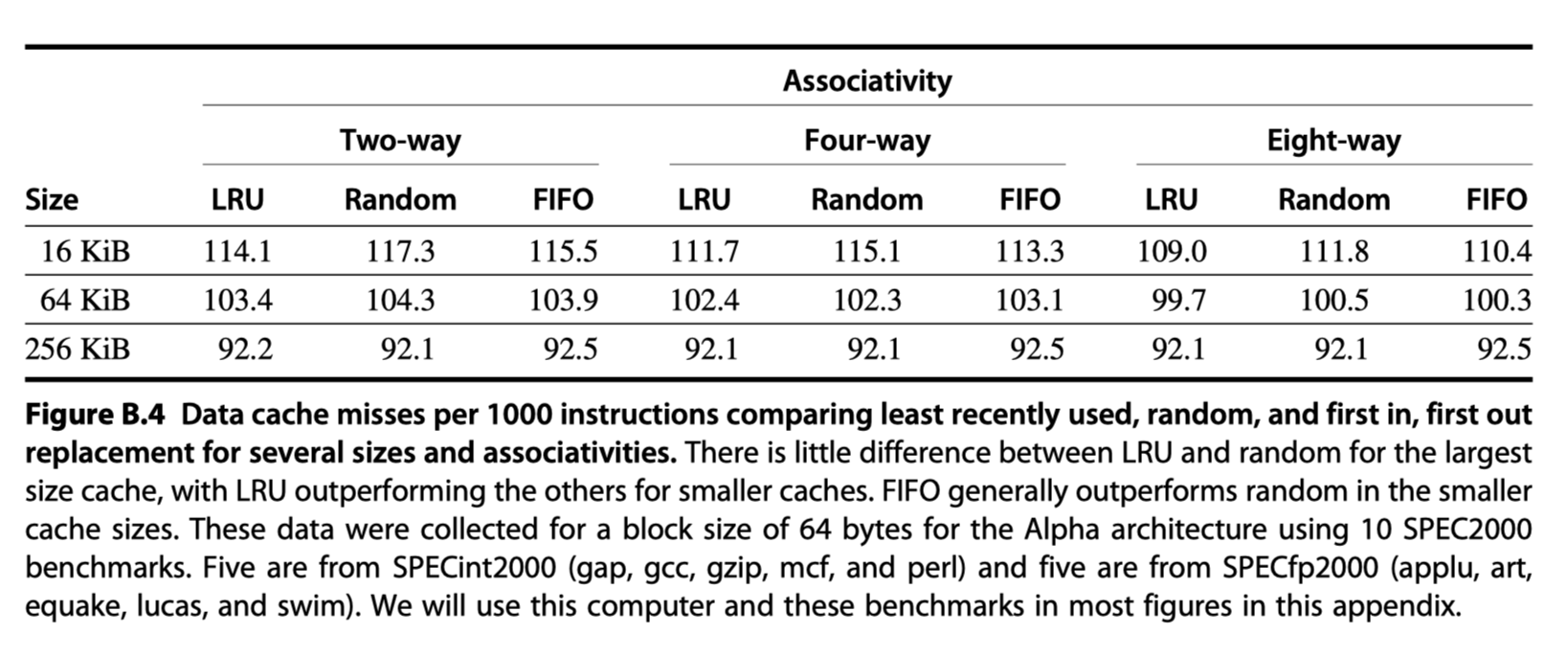
Q3: Which block should be replaced on a miss? (block replacement)
- Direct mapped placement?: Trivial
- Fully associative or set-associative?
- Random: Simple to build hardware
- Least recently used (LRU): Expensive
- Pseudo LRU: One bit per way (way = banks in a set) to record whether it is recently used or not
- First in, first out (FIFO)
-
Q4: What happens on a write? (write strategy)
- Reads dominate processor cache accesses. But, cannot neglect writes (~7% of the overall memory traffic)
- Read vs Write:
- Read:
- The block can be read from the cache at the same time that the tag is read and compared. If miss, then just ignore the value read
- Can read more bytes than necessary
- Write:
- Always need to check tag first to see if it is hit
- Always need to specify the bytes (usually, 1~8 bytes) in the block you want to write
- Read:
- Two basic write options
- Write through:
- Write to the cache and the lower-level memory
- Cache is always clean
- Easier to implement than write back
- Simplify data coherency: Good for multiprocessors and I/Os
- To reduce write stall, write buffer allows the processor to continue as soon as the data are written to the buffer.
- Write back:
- Write to the cache only. Write to main level memory only if it is replaced from cache
- Less memory bandwidth and energy
- Dirty bit: If the block is clean (not modified), the block is not written back when it is replaced.
- Write through:
- Two write miss policy options
- Write allocate:
- The block is allocated on a write miss
- Often used by write-back cache
- No-write allocate:
- The block is not allocated in cache. Directly write on main memory.
- Often used by write-through cache
- Write allocate:
An Example: The Opteron Data Cache
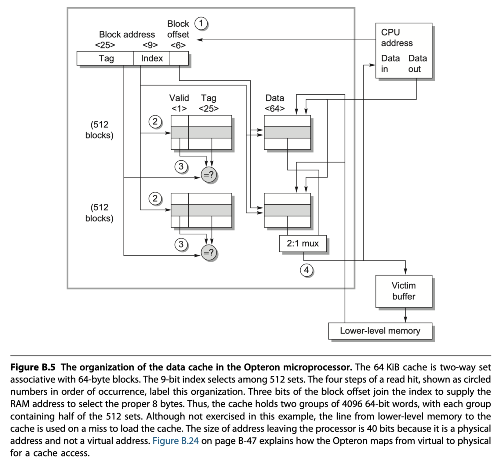
- AMD Opteron microprocessor
- 64KB cache
- 64-byte blocks ($2^6$ bytes) with two-way set associative placement (512=$2^9$ sets)
- LRU replacement
- Write back
- Write-allocate on write miss
- Handling Read
- Step 1: Address division
- 48-bit virtual address
- $\rightarrow$ 40-bit physical address
- $\rightarrow$ 34-bit block address + 6-bit block offset
- $\rightarrow$ 34-bit block address = 25 Tag + 9 Index
- $Index\,bits$ $= log(\frac{Cache\,size}{Block\,size\times Set\,associativity})$
- Step 2: Select a set according to the cache index and read two tags (because it is 2-way set associative cache)
- Step 3: Compare the two tags and tag-portion of the block address from the processor + Check valid bits
- Step 4: Assume cache hit. Then select the winning data and send signal to the processor to load the data from the cache.
- 2 Clock cycles for step 1~4
- If miss?
- Signal to the processor
- Read 64 bytes from the next level of the hierarchy
- Step 1: Address division
- Handling Write
- Step 1-3 same with read
- Opteron is OoO, so it writes to the cache only if the instruction has committed and the cache tag comparison indicates a hit
- If miss?
- Check dirty bits
- If the victim was modified, its data and address are sent to the victim buffer (~ write buffer). And, the victim buffer writes to the lower-level of hierarchy.
- If victim buffer is full, the cache must wait
- Divide a cache to an instruction cache and a data cache to avoid structural hazard for load/store
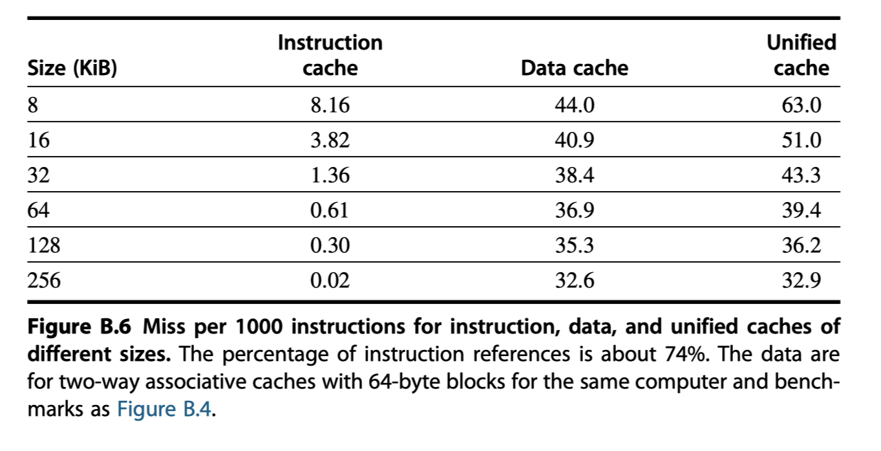
Cache Performance
- A better measure of memory hierarchy performance than miss rate?
- Average memory access time = Hit time $+$ Miss rate $\times$ Miss penalty
- eg. Splitting instruction and data caches is better than unified cache in terms of average memory access time
Average Memory Access Time and Processor Performance

-
Include hit clock cycles in CPU execution clock cycles
-
Impact of cache miss: Larger for lower $CPI_{execution}$ and higher clock frequency
Miss Penalty and Out-of-Order Execution Processors
- How to define “miss-penalty” for out-of-order processors? $\rightarrow$ Non-overlapped latency
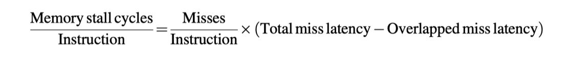
- Miss latency factors
- Length of memory latency
- Length of latency overlap
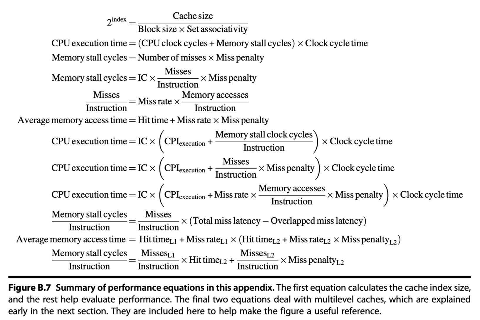
- Cache equations in this appendix
Six Basic Cache Optimizations
-
Average memory access time = Hit time $+$ Miss rate $\times$ Miss penalty
- Optimization categories
- Reducing the miss rate
- Large block size, larger cache size, higher associativity
- Reducing the miss penalty
- Multi-level caches, giving reads priority over writes
- Reducing the time to hit in the cache
- Avoiding address translation when indexing the cache
- Reducing the miss rate
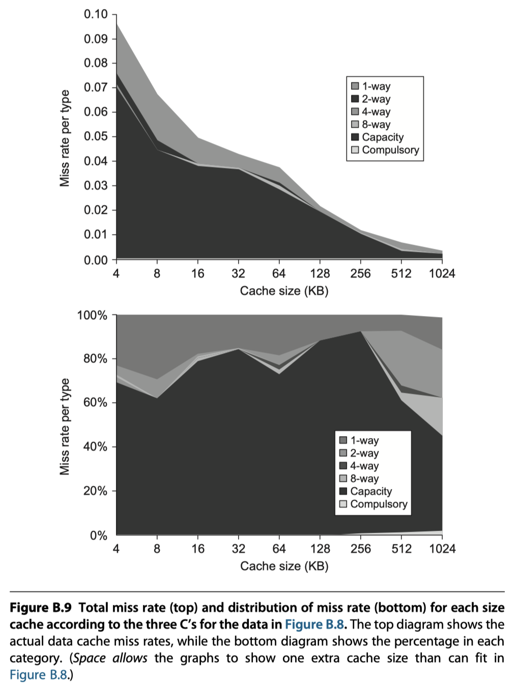
- The causes of misses (Three C’s)
- Compulsory: Cold-start misses or first-reference misses
- Capacity: If cache cannot contain all blocks
- Conflict: If not (expensive) fully-associated and if there exist some popular sets $\rightarrow$ Conflict misses, collision misses
- Too many misses $\rightarrow$ The memory hierarchy is said to thrash
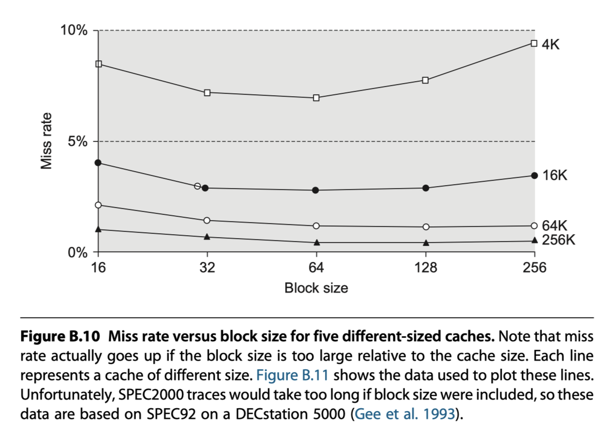
First Optimization: Larger Block Size to Reduce Miss Rate
- The simplest way
- Trade-off for to different block size
Second Optimization: Larger Caches to Reduce Miss Rate
Third Optimization: Higher Associativity to Reduce Miss Rate
- Two rules of thumb from Figure B.9
- (1) Eight-way set associative is for practical purposes as effective in reducing misses for these sized caches as fully associative.
- (2) The 2:1 cache rule of thumb: A direct mapped cache of size N has about the same miss rate as a two-way set associative cache of size N/2.
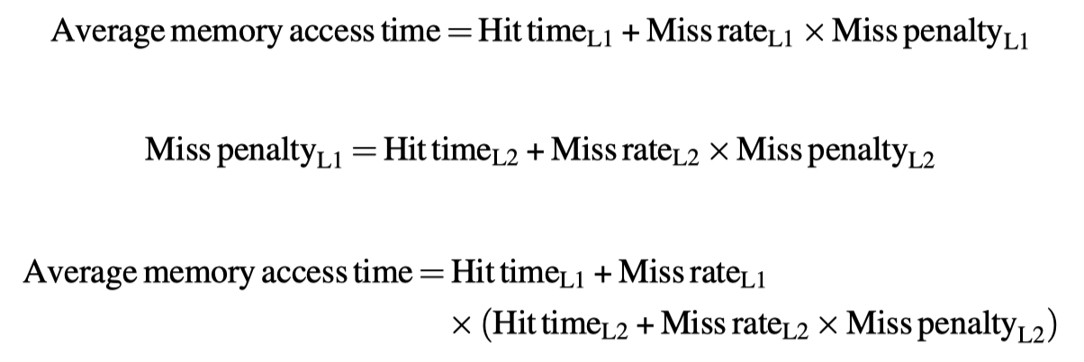
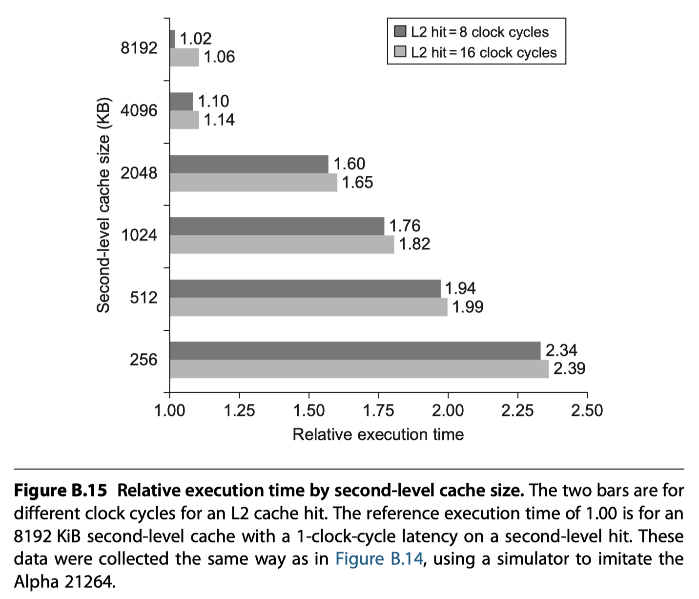
Fourth Optimization: Multilevel Caches to Reduce Miss Penalty
-
The first-level cache can be small enough to match the clock cycle time of the fast processor.
-
Yet, the second-level cache can be large enough to capture many accesses that would go to main memory, thereby lessening the effective miss penalty.
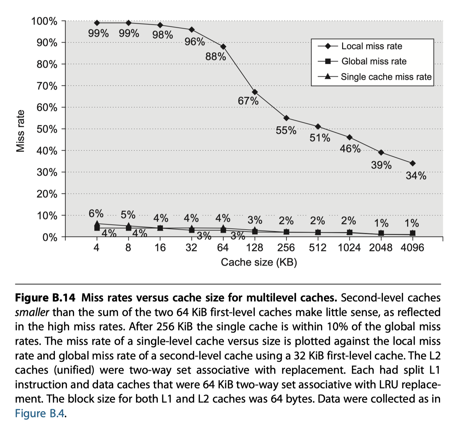
- Set-associativity in the second level cache to reduce miss rate
- Multilevel inclusion (Data in the first level cache is included in the second level)
- Desirable because of consistency between I/O an caches or among caches in a multiprocessor
Fifth Optimization: Giving Priority to Read Misses over Writes to Reduce Miss Penalty
- Most important optimization for write-through cache is to add a write buffer with proper size
- The write buffer may need to hold the updated value of a location needed on a read miss
- Example
- Write a block to a direct-mapped, write-through cache
- The block is replaced with other data and written to a write buffer
- If the same block is requested by the processor followed by read-miss before the write buffer complete to update main memory, then RAW hazard!
- Easy solution
- Wait until the write buffer complete to update the main memory
- Widely accepted solution
- Check the contents of the write buffer on a read miss,
- And if there are no conflicts and the memory system is available,
- Let the read miss continue
- i.e. Give reads priority over writes
Sixth Optimization: Avoiding Address Translation During Indexing of the Cache to Reduce Hit Time
-
Even a small and simple cache must cope with the translation of a virtual address from the processor to a physical address to access memory.
- The guideline of making the common case fast suggests that we use virtual addresses for the cache,
- because hits are much more common than misses.
- Such caches are termed virtual caches, with physical cache used to identify the traditional cache that uses physical addresses.
- It is important to distinguish two tasks:
- Indexing the cache and
- Comparing addresses
- The issues are whether a virtual or physical address is used to index the cache
- and whether a virtual or physical address is used in the tag comparison.
- Full virtual addressing for both indices and tags eliminates address translation time from a cache hit. Then why doesn’t everyone build virtually addressed caches?
- Reason1) Protection
- Page-level protection is checked as part of the virtual to physical address translation, and it must be enforced no matter what.
- Reason2) Every time a process is switched, the virtual addresses refer to different physical addresses, requiring the cache to be flushed $\rightarrow$ Worsen miss rate
- Solution: Add PID (Process-identifier tag) to the cache address tag
- It only need flush the cache when a PID is recycled
- Reason3) Operating systems and user programs may use two different virtual addresses for the same physical address: Aliases or synonyms
- If one is modified, the other is the wrong value
- Physical cache doesn’t have this problem
- Hardware solution: Antialiasing
- Guarantee every cache block a unique physical address
- Software solution:
- By forcing aliases to share some address bits
- eg. Page coloring (Aliases share the last 18-bits) = Set-associative mapping applied to the virtual memory
- Reason4) I/O
- I/O typically uses physical addresses and thus would
- require mapping to virtual addresses to interact with a virtual cache.
- Reason1) Protection
- The best of both virtual and physical caches is to use part of the page offset to index the cache.
- Page offset: the part that is identical in both virtual and physical addresses
- At the same time as the cache is being read using that index, the virtual part of the address is translated, and the tag match uses physical addresses.
- The limitation of this virtually indexed, physically tagged alternative is that a direct-mapped cache can be no bigger than the page size.
- Associativity can keep the index in the physical part of the address and yet still support a large cache
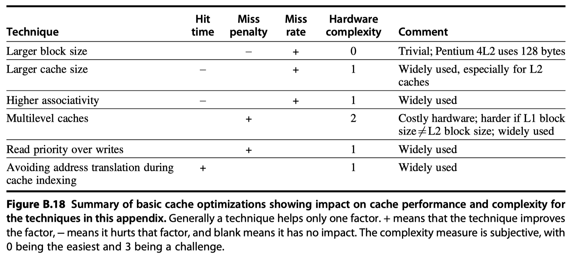
Summary of Basic Cache Optimization
Virtual Memory
- Why virtual memory?
- A computer running multiple processes
- Each process has its own address space, just a small part of memory
- Too expensive to dedicate a full address space of memory for each process
- Share a smaller amount of physical memory among many processes
- Virtual memory
- Divides physical memory into blocks and
- allocate them to different processes
- Reduce the time to start a program
- Protection scheme
- Restricts a process to the blocks belonging only to that process
-
Automatically manages memory hierarchy (eg. the two levels of memory and storage)
-
Mapping of virtual memory to physical memory for a program with four pages
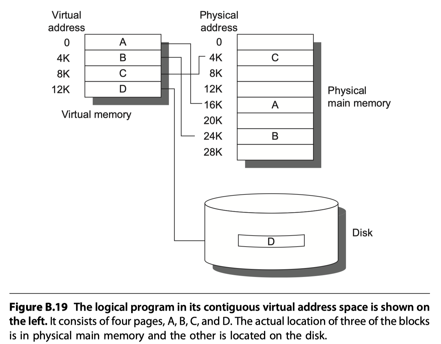
- Relocation
- Virtual memory simplifies loading the program for execution
- The program in Figure B.19 can be placed anywhere in physical memory or disk just by changing the mapping between them
- Alternatively, software can change all address in a program each time
- Virtual memory $\leftrightarrow$ Cache analogy
| Cache | Virtual memory |
|---|---|
| Block/Line | Page or Segment |
| Hardware cache | Main memory |
| Miss | Page fault or address fault |
- Memory mapping or address translation
- With virtual memory, the processor produces virtual addresses that are translated by a combination of hardware and software to physical addresses
- Today, the two memory hierarchy levels controlled by virtual memory are DRAMs and magnetic disks.
- Difference between Cache and Virtual memory
- Replacement :
- On cache misses $\rightarrow$ Controlled by hardware
- Virtual memory replacement $\rightarrow$ Controlled by operation system for better decision
- Size:
- The size of processor address determines the size of virtual memory
- Cache size is independent of the processor address size
- Secondary storage is also used for the file system, not include din the address space
- Replacement :
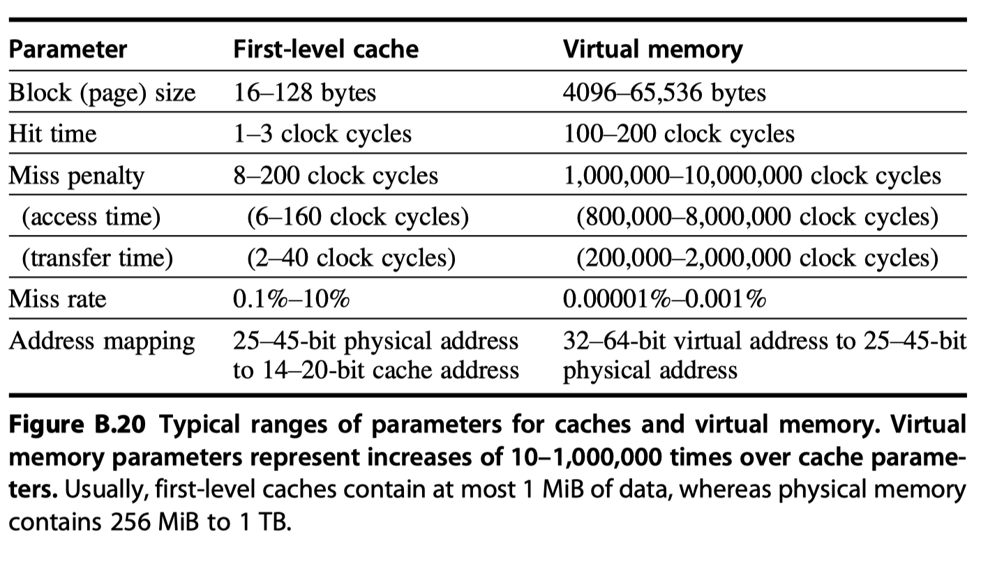
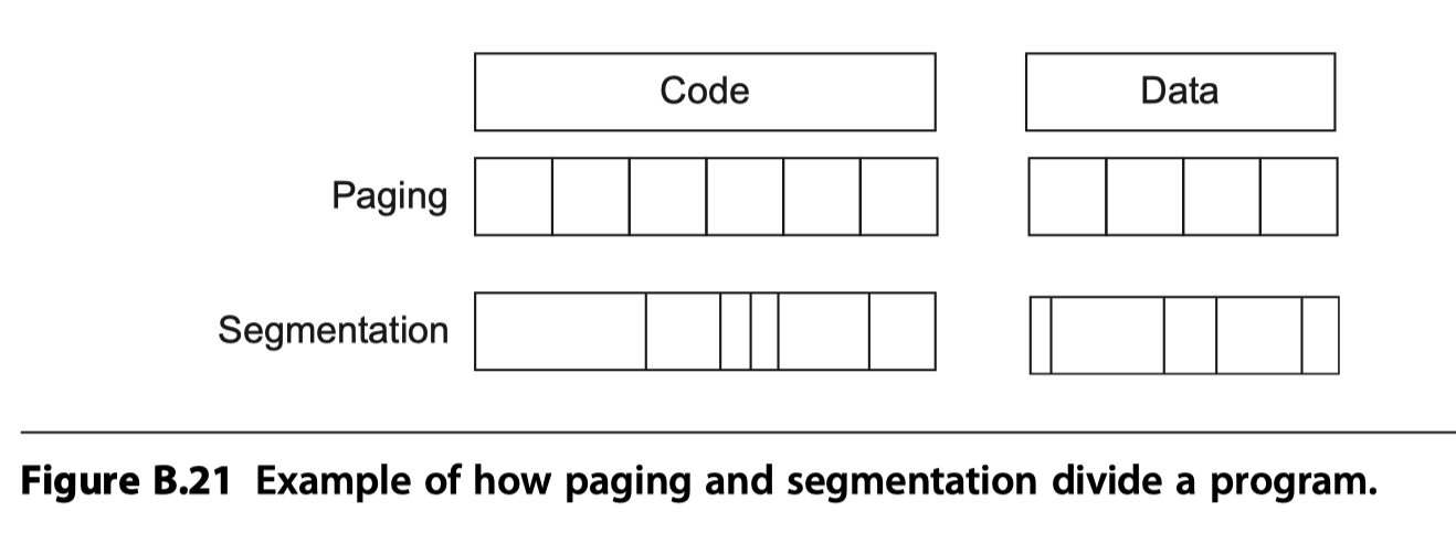
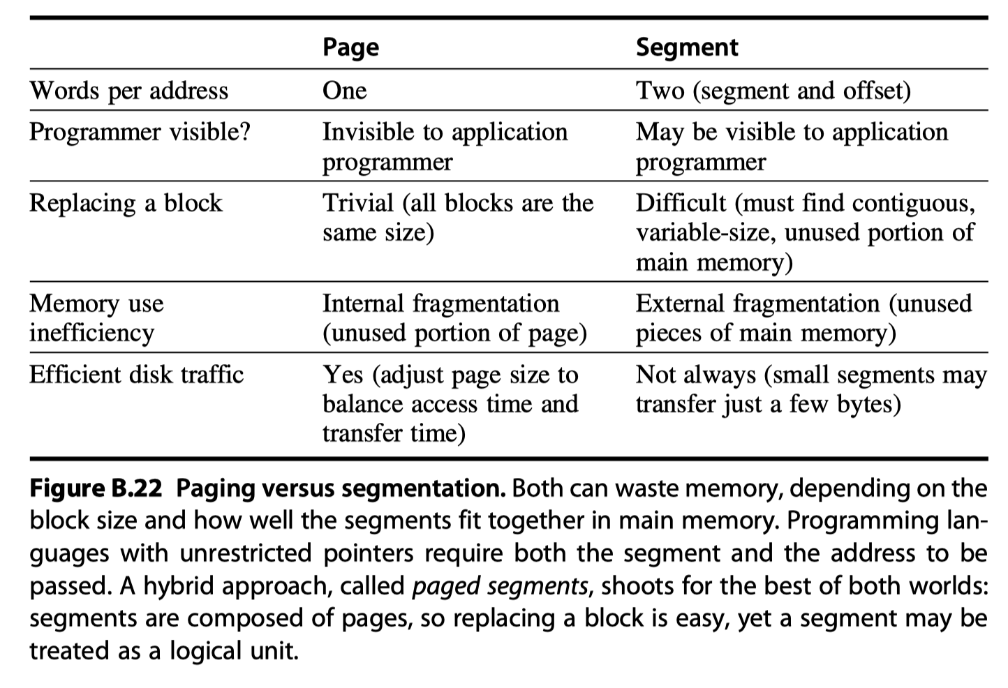
- Block size in virtual memory
-
Fixed size block = Pages (4~8KB)
- Paged addressing $\rightarrow$ Single fixed-size address = page number + offset within a page
-
Variable size blocks = Segments (~ $2^{16}$ up to $2^{32}$ bytes)
- Segmented addressing $\rightarrow$ 1 word for segment number + 1 word for an offset within a segment
-
Fixed size block = Pages (4~8KB)
Four Memory Hierarchy Questions Revisited
- Q1: Where Can a Block be Placed in Main Memory?
- To reduce the miss rate, operating systems allow blocks to be placed anywhere in main memory
- i.e. Fully associative
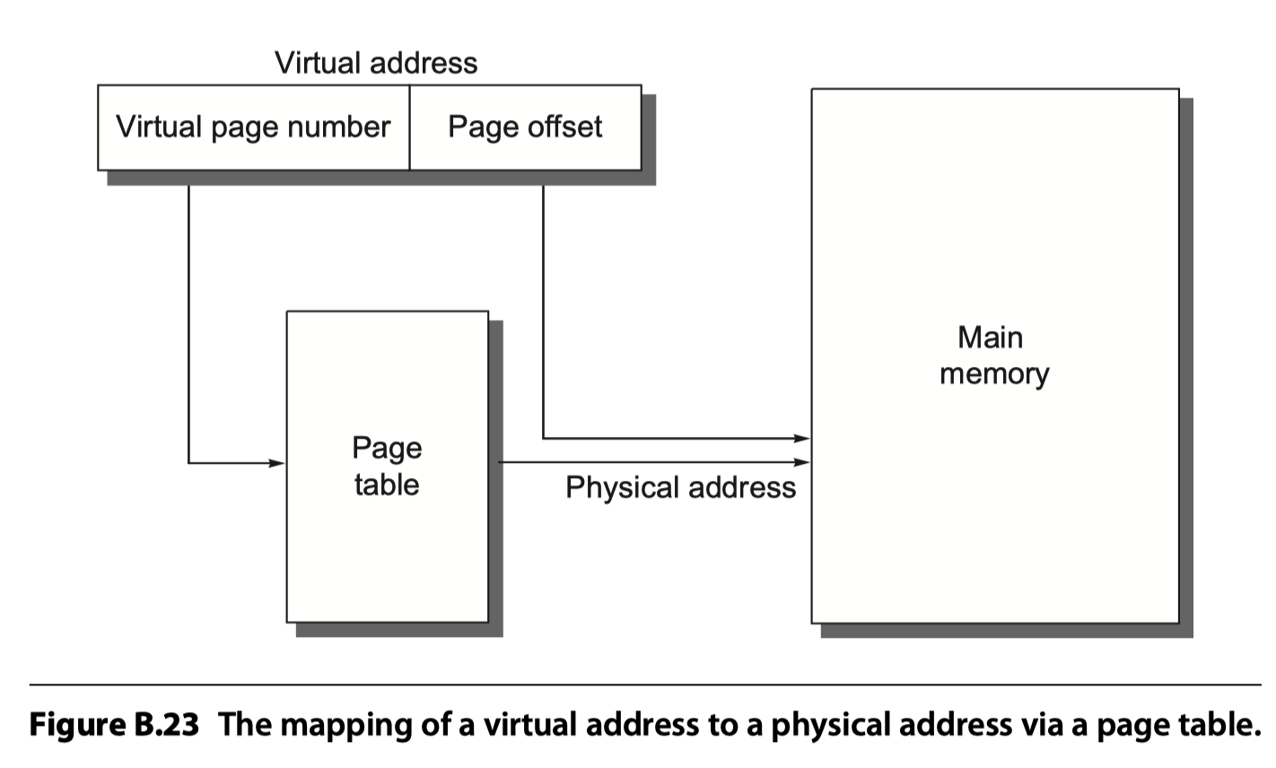
- Q2: How Is a Block Found If It Is in Main Memory?
- For paging (accessing data in a page), the page offset is simply concatenated to this physical page address (see Figure B.23).
-
Page table
- Indexed by the virtual page number, the size of the table is the number of pages in the virtual address space.
- Given a 32-bit virtual address, 4 KiB ($2^{12}$) pages, and 4 bytes per page table entry (PTE), the size of the page table would be $(2^{32}/2^{12})\times2^2=2^{22}$ or 4 MiB
- cf. Inverted page table: Apply hashing function to virtual address to save page table size
-
Translation lookaside buffer (TLB) or translation buffer
- A cache dedicated to the address translation
- Q3: Which Block Should be Replaced on a Virtual Memory Miss?
- Almost all OS try to replace the least recently use (LRU) block
- “Use bit” or “Reference bit” like LRU in cache
- Q4: What Happens on a Write?
- Always write-back. Write-through is extremely expensive
Techniques for Fast Address Translation
-
Page tables are usually so large that they are stored in main memory and are sometimes paged themselves.
- Paging means that every memory access logically takes at least twice as long,
- with one memory access to obtain the physical address and
- a second access to get the data.
- Translation look aside buffer (TLB), also called a translation buffer (TB).
- By keeping address translations in a special cache, a memory access rarely requires a second access to translate the data. This special address translation cache is referred to as a
- A TLB entry is like a cache entry where
- the tag holds portions of the virtual address and
- the data portion holds
- a physical page frame number,
- protection field,
- valid bit,
- use bit, and
- dirty bit (which means that the corresponding page is dirty)
- To change the physical page frame number or protection of an entry in the page table, the operating system must make sure the old entry is not in the TLB
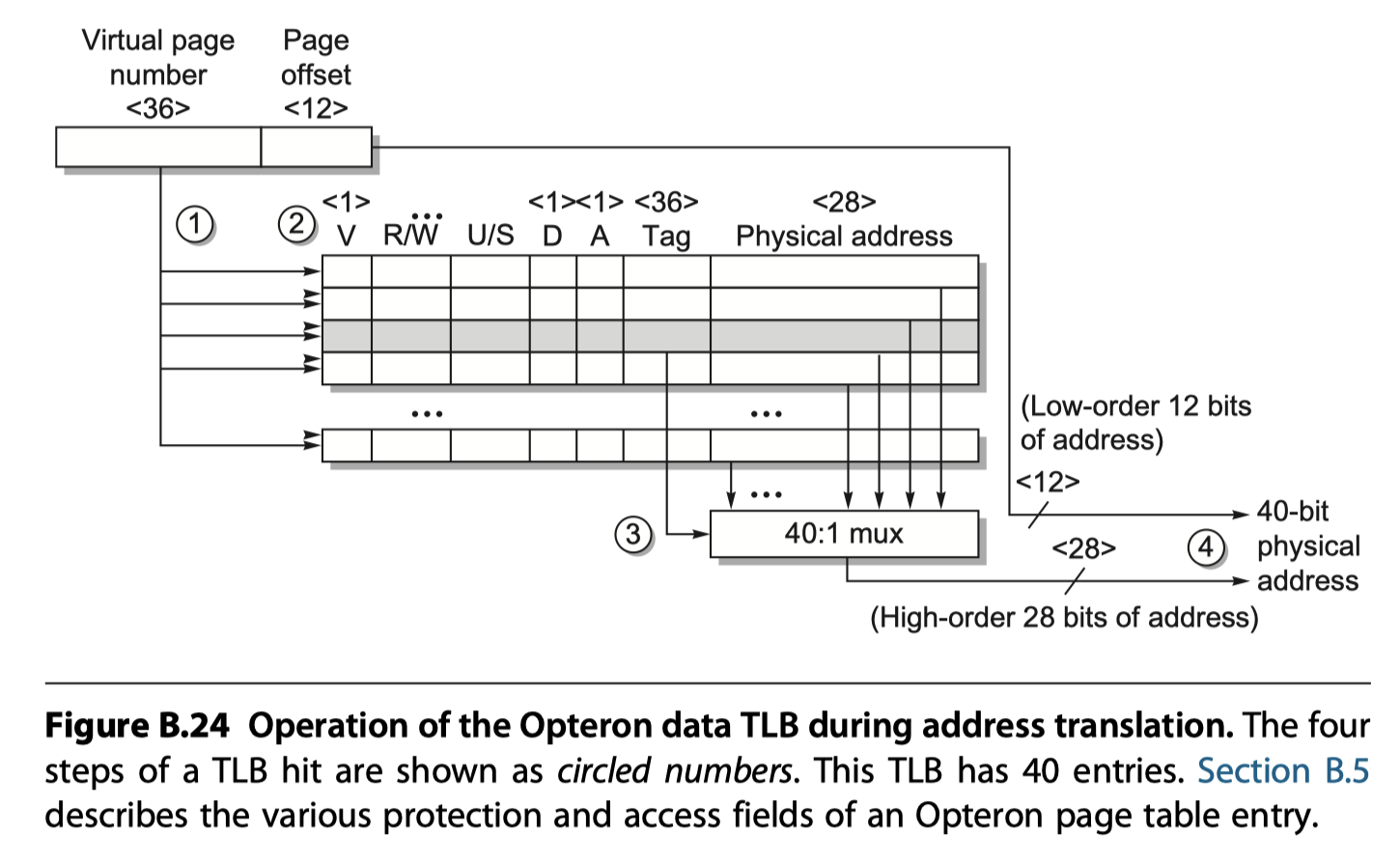
- Opteron data TLB organization
- Fully associative placement
- (Step 1, 2) Translation begins by sending the virtual address to all tags that are marked valid
- (Step 2) Type of memory access is checked for a violation against protection information in TLB
- (Step 3) Matching tag sends the corresponding physical address via a 40:1 MUX
- (Step 4) The page offset $+$ the physical page frame $\rightarrow$ A full physical address
Selecting a Page Size
- Why larger page!
- $Page \,table\, size \,\propto\, 1/(Page \,size)$ $\rightarrow$ Larger page size saves memory space for page table
- Large page size allows larger caches with fast cache hit time
- Transferring larger pages, possibly over a network, is more efficient than transferring smaller pages.
- #TLB entries is restricted $\rightarrow$ Large pages $\rightarrow$ More memory can be mapped
- Why smaller page!
- Conserve storage (Not to lose remainder in the storage with contiguous alignment of pages)
- i.e. Internal fragmentation
- Process start-up time
- Conserve storage (Not to lose remainder in the storage with contiguous alignment of pages)
Summary of Virtual Memory and Caches
- Figure B.25: a hypothetical example going from a 64-bit virtual address to a 41-bit physical address with two levels of cache. This L1 cache is virtually indexed, and physically tagged because both the cache size and the page size are 8 KiB ($2^{13}$). The L2 cache is a direct mapped 4 MiB ($2^{22}$). The block size for both is 64 bytes ($2^6$).
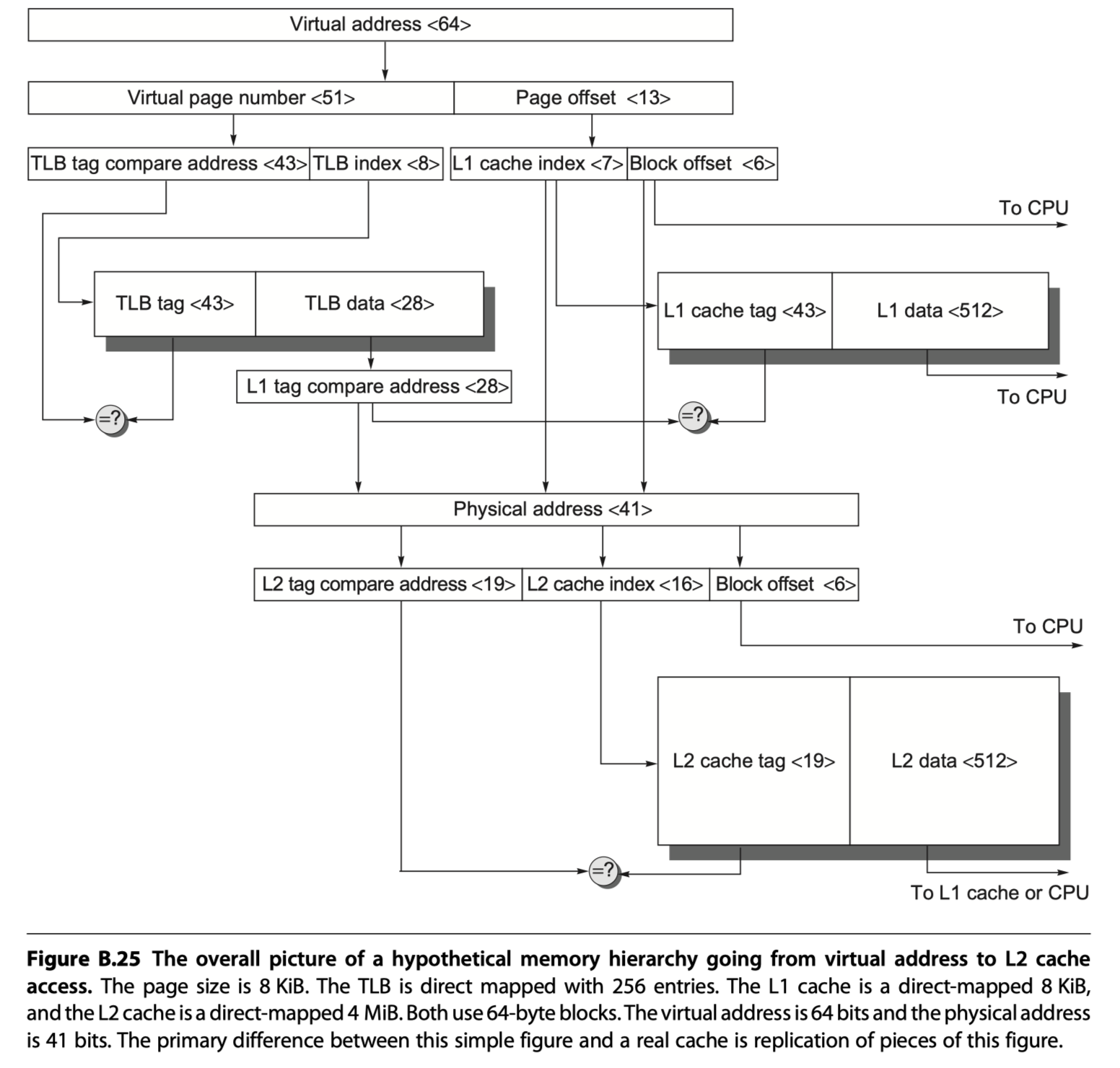
- Virtual address <64> $\rightarrow$ virtual page number <51> + page offset <13>
- Page offset <13> $\rightarrow$ L1 cache index <7> (select a set in L1 cache)+ Block offset <6>
- Virtual page number <51> $\rightarrow$ TLB $\rightarrow$ TLB tag compare address <43> + TLB index <8> $\rightarrow$ L1 tag compare address <28>
- L1 tag compare address (Physical address of the page) <28> ?= L1 cache tag <43>
- If hit, L1 cache select the word by using block offset <6> and send it to the processor
- If miss, the physical address is used to try the L2 cache where ,
- L1 tag compare address <28> + L1 cache index <7> + Block offset <6> $\rightarrow$ Physical address <41>
- Physical address <41> $\rightarrow$ L2 tag compare address <19> + L2 cache index <16> + Block offset <6>
- L2 cache: Direct-mapped 4MiB ($2^{22=16+6}$)
Protection and Examples of Virtual Memory
-
Safe multiprogramming $\rightarrow$ Protection and sharing among programs!
-
Multiprogramming leads to the concept of a process.
-
Metaphorically, a process is a program’s breathing air and living space—that is, a running program plus any state needed to continue running it.
-
Process switch or context switch
- Allow time-sharing of concurrent execution and resource allocation with several interactive users at the same time
- The computer designer must ensure that the processor portion of the process state can be saved and restored.
- The operating system designer must guarantee that processes do not interfere with each others’ computations.
Protecting Processes
- Simple:
- Processes can be protected by having their own page tables, each pointing to distinct pages of memory
-
Ring:
- Like a military classification system of top secret, secret, confidential, and unclassified, concentric rings of security levels allow the most trusted to access anything, the second most trusted to access everything except the innermost level, and so on.
-
Keys and locks:
- A program can’t unlock access to the data unless it has the key. For these keys, or capabilities, to be useful, the hardware and operating system must be able to explicitly pass them from one program to another without allowing a program itself to forge them. Such checking requires a great deal of hardware support if time for checking keys is to be kept low.
- Two of the options:
- The older segmented address space
- The newer flat, 64-bit address space.
A Segmented Virtual Memory Example: Protection in the Intel Pentium
- IA-32: Protection scheme in Intel 8086 architectures
- Four levels of protection
- The innermost level (0) corresponds to the traditional kernel mode, and the outermost level (3) is the least privileged mode.
- Separate stacks for each level to avoid security breaches between the levels
- Divides the address space,
- allowing both the operating system and the user access to the full space
- The IA-32 user can call an operating system routine in this space and even pass parameters to it while retaining full protection
- IA-32 allows the operating system to maintain the protection level of the called routine for the parameters that are passed to it.
- This potential loophole in protection is prevented by not allowing the user process to ask the operating system to access something indirectly that it would not have been able to access itself. (Such security loopholes are called Trojan horses.)
- Four levels of protection
- Adding Bounds Checking and Memory Mapping
- The first step in enhancing the Intel processor was getting the segmented addressing to check bounds as well as supply a base
- Rather than a base address, the segment registers in the IA-32 contain an index to a virtual memory data structure called a descriptor table
- Descriptor tables play the role of traditional page tables
- On the IA-32 the equivalent of a page table entry is a segment descriptor
- Adding Sharing and Protection
- To provide for protected sharing,
- half of the address space is shared by all processes and half is unique to each process, called global address space and local address space, respectively
- To provide for protected sharing,
- Adding Safe Calls from User to OS Gates and Inheriting Protection Level for Parameters
- Allowing the user to jump into the operating system is a bold step.
- How, then, can a hardware designer increase the chances of a safe system without trusting the operating system or any other piece of code?
- The IA-32 approach is to restrict where the user can enter a piece of code, to safely place parameters on the proper stack, and to make sure the user parameters don’t get the protection level of the called code.
A Paged Virtual Memory Example: The 64-Bit Opteron Memory Management
- A flat, 32-bit address space introduced by 80386
- which sets all the base values of the segment registers to zero.
- AMD dispensed with the multiple segments in the 64-bit mode.
- It assumes that the segment base is zero and ignores the limit field. The page sizes are 4 KiB, 2 MiB, and 4 MiB.
- The 64-bit virtual address of the AMD64 architecture is mapped onto 52-bit physical addresses
- You can implement fewer bits to simplify hardware
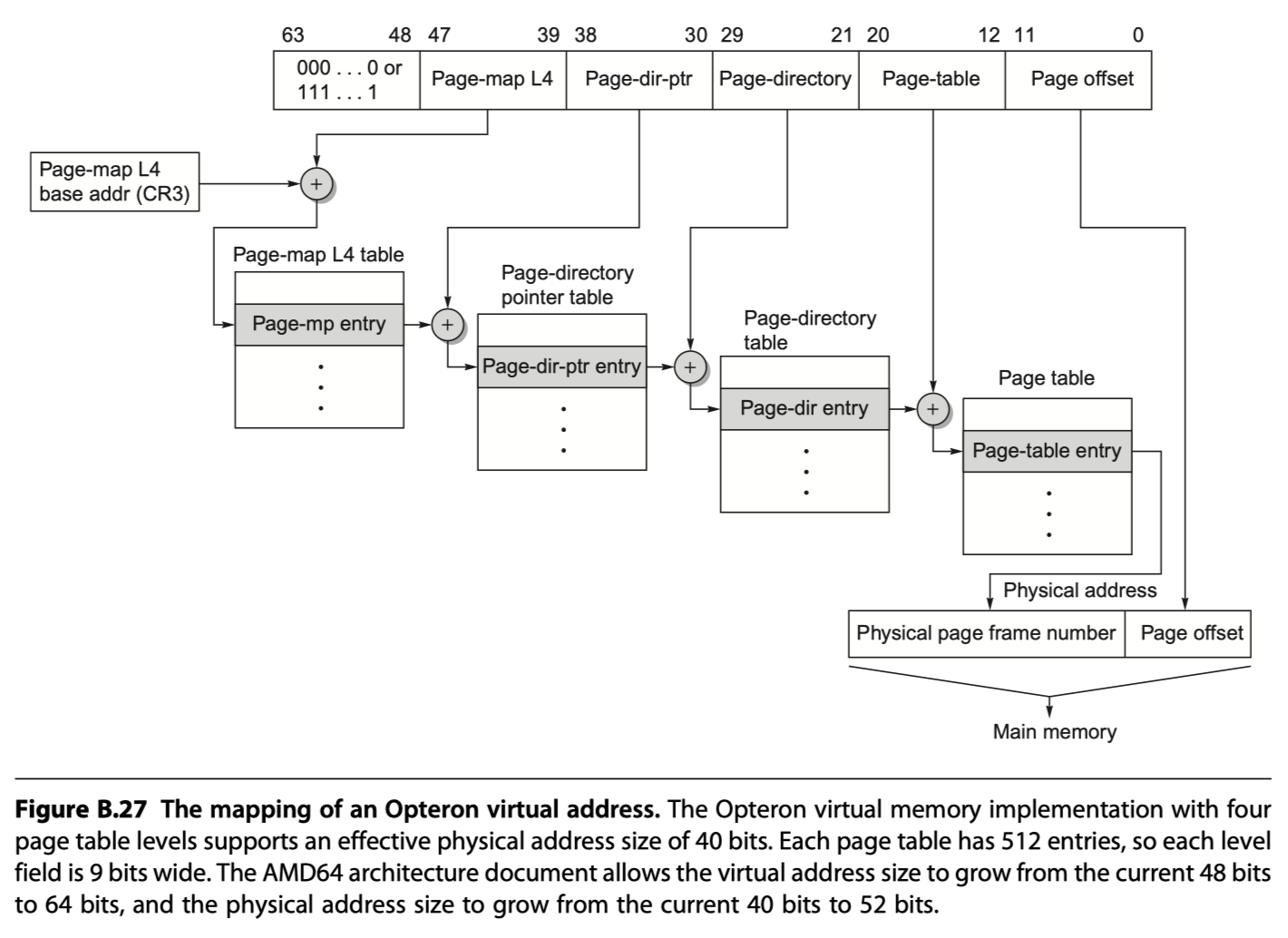
- The size of page tables for the 64-bit address space is alarming. Hence, AMD64 uses a multilevel hierarchical page table to map the address space to keep the size reasonable.
- The offsets for each of these page tables come from four 9-bit fields. Address translation starts with adding the first offset to the page-map level 4 base register and then reading memory from this location to get the base of the next-level page table.
- The next address offset is in turn added to this newly fetched address, and memory is accessed again to determine the base of the third page table. It happens again in the same fashion. The last address field is added to this final base address, and memory is read using this sum to (finally) get the physical address of the page being referenced. This address is concatenated with the 12-bit page offset to get the full physical address. Note that the page table in the Opteron architecture fits within a single 4 KiB page.

- What prevents the user from creating illegal address translations and getting into mischief?
- The page tables themselves are protected from being written by user programs.
- Thus, the user can try any virtual address, but by controlling the page table entries the operating system controls what physical memory is accessed.
- Sharing of memory between processes is accomplished by having a page table entry in each address space point to the same physical memory page.
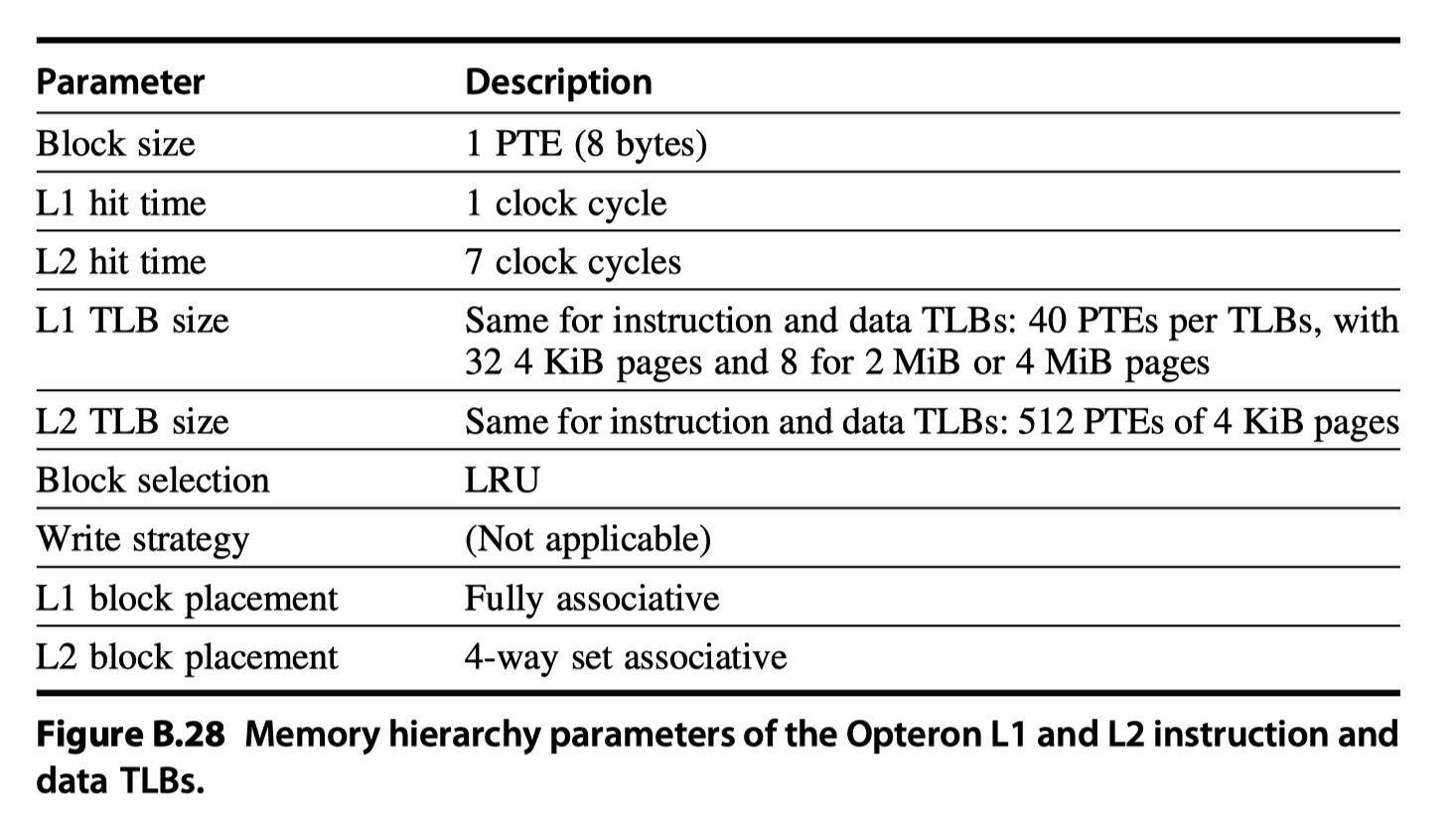
- The Opteron employs four TLBs to reduce address translation time, two for instruction accesses and two for data accesses. Like multilevel caches, the Opteron reduces TLB misses by having two larger L2 TLBs: one for instructions and one for data. Figure B.28 describes the data TLB.
Reference
- Appendix B in Computer Architecture A Quantitative Approach (6th) by Hennessy and Patterson (2017)
- Notebook: Computer Architecture Quantitive Approach
Notes Mentioning This Note
Table of Contents
- Review of Memory Hierarchy
- Introduction
- Cache Performance
-
Six Basic Cache Optimizations
- First Optimization: Larger Block Size to Reduce Miss Rate
- Second Optimization: Larger Caches to Reduce Miss Rate
- Third Optimization: Higher Associativity to Reduce Miss Rate
- Fourth Optimization: Multilevel Caches to Reduce Miss Penalty
- Fifth Optimization: Giving Priority to Read Misses over Writes to Reduce Miss Penalty
- Sixth Optimization: Avoiding Address Translation During Indexing of the Cache to Reduce Hit Time
- Summary of Basic Cache Optimization
- Virtual Memory
- Protection and Examples of Virtual Memory
- Reference